


1083286-UIM-L-1219
Johnson Controls Ducted Systems
9
SECTION III: FILTERS
FILTER INSTALLATION
All applications require the use of a field installed filter. All filters and
mounting provision must be field supplied.
Filters must be installed external to the furnace cabinet.
DO NOT
attempt to install filters inside the furnace.
1. Air velocity through throwaway type filters may not exceed 300 feet per min-
ute (91.4 m/min). All velocities over this require the use of high velocity filters.
2. Do not exceed 1800 CFM using a single side return and a 16x25 filter. For
CFM greater than 1800, you may use two side returns or one side and the
bottom or one side return with a transition to allow use of a 20x25 filter.
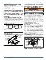
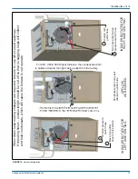
SIDE RETURN
Locate the “L” shaped corner locator's. These indicate the size of the
cutout to be made in the furnace side panel. Refer to Figure 9.
Install the side filter rack following the instructions provided with that
accessory. If a filter(s) is provided at another location in the return air
system, the ductwork may be directly attached to the furnace side
panel.
HORIZONTAL FILTERS
Any branch duct (rectangular or round duct) attached to the plenum
must attach to the vertical plenum before the filter. The use of straps
and/or supports is required to support the weight of the external filter
box.
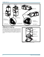
DOWNFLOW FILTERS
Downflow furnaces typically are installed with the filters located above
the furnace, extending into the return air plenum or duct. Any branch
duct (rectangular or round duct) attached to the plenum must attach to
the vertical plenum above the filter height.
Filter(s) may be located in the duct system external to the furnace using
an external duct filter box attached to the furnace plenum or at the end
of the duct in a return filter grille(s). The use of straps and/or supports is
required to support the weight of the external filter box.
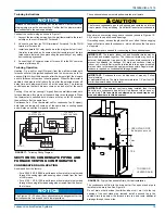
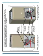
SECTION IV: GAS PIPING
GAS SAFETY
CAUTION
All filters and mounting provision must be field supplied. All installa-
tions must have a filter installed.
NOTICE
Single side return above 1800 CFM is approved as long as the filter
velocity does not exceed filter manufacturer’s recommendation and a
transition is used to allow use on a 20x25 filter.
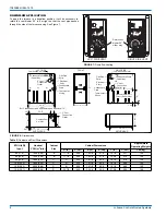
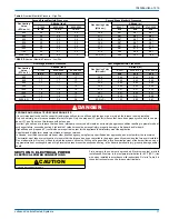
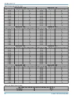
Table 3:
Recommended Filter Sizes (High Velocity 600 FPM)
CFM (m³/min)
Cabinet Size
Side (in)
Bottom (in)
1200 (34.0)
B
16 x 25
16 x 25
1600 (45.3)
C
16 x 25
20 x 25
2000 (56.6)
C
(2) 16 x 25
20 x 25
2000 (56.6)
D
(2) 16 x 25
22 x 25
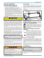
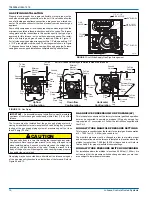
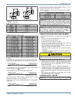
FIGURE 9:
Side Return Cutout Markings
IMPORTANT:
Some accessories such as electronic air cleaners and
pleated media may require a larger side opening. Follow the instruc-
tions supplied with that accessory for side opening requirements. Do
not cut the opening larger than the dimensions for the “Optional
Return Air Cutout” shown in Figure 8.
!
Front of
Furnace
Corner
Markings
Side of
Furnace
DANGER
An overpressure protection device, such as a pressure regulator,
must be installed in the gas piping system upstream of the furnace
and must act to limit the downstream pressure to the gas valve so it
does not exceed 0.5 psig (14" w.c., 3.48 kPa). Pressures exceeding
0.5 psig (14” w.c., 3.48 kPa) at the gas valve will cause damage to the
gas valve, resulting in a fire or explosion or cause damage to the fur-
nace or some of its components that will result in property damage
and loss of life.
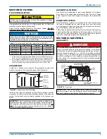
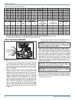
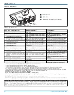
FIGURE 10:
Gas Valve
IMPORTANT:
Plan the gas supply routing before determining the
correct gas pipe entry. Use 90-degree conventional elbow(s) and
short pipe nipples to enter through the cabinet access holes.
!
INLET
WRENCH
BOSS
INLET
PRESSURE
PORT
ON OFF
SWITCH
LOW STAGE REGULATOR
ADJUSTMENT
OUTLET
OUTLET
PRESSURE
PORT
VENT
PORT
HIGH STAGE REGULATOR
ADJUSTMENT


