M9000-310 and M9000-320 Series Weather Shield Enclosures Installation Instructions
4
Mounting
The M9000-310 and M9000-320 Weather Shield
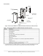
Enclosure Kits are shipped from the factory partially
assembled, with the cover held in place using the four
cover screws included with the kit. The remainder of
the parts required for mounting can be found inside the
enclosure.
Control Damper Applications
Mount the weather shield enclosure onto a control
damper as follows:
1.
Loosen the four cover screws using a No.1 Phillips
screwdriver and remove the cover and gasket
assembly from the enclosure base.
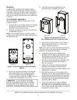
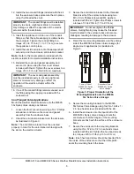
2.
Orient the anti-rotation bracket onto the enclosure
as illustrated in Figure 3.
Note:
The anti-rotation bracket must be oriented
properly for the anti-rotation tab to align with the slot on
the electric actuator.
3.
Secure the anti-rotation bracket to the threaded
brass inserts of the enclosure base using two
M3 x 8 mm Phillips screws and M4 washers
included with the kit. Tighten the Phillips screws to
a torque of 15 to 20 lb·in (1.7 to 2.3 N·m).
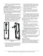
4.
Orient the two mounting brackets onto the
enclosure base as illustrated in Figure 4.
5.
Secure the mounting brackets to the enclosure
base using four No. 12-24 x 1/2 in. hex-head
screws (included with the kit).
Note:
Each hex-head screw should be inserted from
the inside of the enclosure so that the nitrile patch
seals the mounting hole in the base.
6.
Install the enclosure and mounting bracket
assembly onto the damper shaft extension. Orient
the assembly so that the flanges of the mounting
brackets are flush with the mounting surface.
7.
Using the mounting brackets as a template, mark
the mounting hole locations with a ball-peen
hammer and punch.
8.
Remove the enclosure and mounting bracket
assembly from the damper shaft extension.
9.
Drill pilot holes at each of the marked spots using a
drill and a No. 10 drill bit.
10. Reinstall the enclosure and mounting bracket
assembly onto the damper shaft extension. Orient
the assembly so that the flanges of the mounting
brackets are flush with the mounting surface and
the holes in the mounting brackets align with the
pilot holes drilled in Step 9.
11. Secure the enclosure and mounting bracket
assembly to the mounting surface using four
No. 12-24 x 1/2 in. hex-head screws included with
the kit. Tighten the hex-head screws to a torque of
20 to 25 lb·in (2.3 to 2.8 N·m).
IMPORTANT:
Do not overtighten the Phillips
screws. Overtightening may cause the threaded
inserts located in the enclosure base to become
dislodged, resulting in damage to the enclosure.
M9000-320
M9000-310
Anti-Rotation
Bracket
Anti-Rotation
Bracket
F
IG
:r
tb
rk
t
Figure 3: Proper Orientation of the Anti-Rotation
Bracket
M9000-320
M9000-310
F
IG
:m
n
tb
rk
t
Figure 4: Proper Orientation of the
Mounting Brackets onto the Enclosure Base


