background image

NCB-EL/FL Configuration

Adding and Binding the NCB-EL/FL to the Echelon Network

54

IFI Routers/Repeaters Installation & Operation Manual - P/N: 53388:Rev: A1  5/5/09

Ether/Plug Application

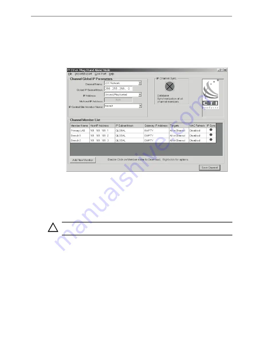
Figure 7.3

 shows the Ether/Plug application’s main screen.

The channel name is the description that was set when the Ether/Plug application was run for 
the first time; it is a description of the TCP/IP network shared by all the NCB-EL/FL routers.

The global IP sub-net mask will depend on the TCP/IP network.  The available settings in the 
drop-down menu for the IP Address will be detailed in the individual examples found in 

Section 8, “NCB-EL/FL Network Applications”, on page 57

.

Figure 7.3  Ether/Plug Application Main Screen

7.2  Adding and Binding the NCB-EL/FL to the Echelon 

Network

NCB-EL routers must be added in the Echelon network like any standard router and bound using 
the Echelon Gateway.  No additional programming is required for the NCB-EL/FL in the Gateway.

7.2.1  Adding a Router

Step 1. Verify that no nodes on the channel that the router is going to be added to are in fault.
Step 2. Verify that the routers on the network are functioning.  Note that if the nodes on the other 

side of the router are not in fault, then the router is functioning.

Step 3. Select Tools >Add Node in the Gateway Configuration Tool, or right-click on the node 

you want to add.

Step 4. Select the desired node number and select the correct connect node.  The Connect Node is 

the node that the router you are adding is connected to.
• If the node is connected through a repeater, then it is the node closest to the Gateway.
• If the node is connected on a DFXC ring, then the connect node is the most recently 

bound node of the nodes the new node is connected to.

Step 5. Select OK, and the new router will be added to the node list.

!

CAUTION: TCP/IP Settings

Configure and connect to the TCP/IP network before binding the router from the Echelon Gateway.

Содержание Intelligent Fire Integrator 4WRMB

Страница 1: ...Intelligent Fire Integrator IFI Routers Repeaters For Johnson Control Echelon Networks Installation Operation Manual Document 53388 5 5 09 Rev A1 P N 53388 A1 ECN 09 347 ...

Страница 2: ...or may not provide adequate warning of a fire Smoke detectors cannot be expected to provide adequate warning of fires caused by arson children playing with matches especially in bedrooms smoking in bed and violent explosions caused by escap ing gas improper storage of flammable materials etc Heat detectors do not sense particles of combustion and alarm only when heat on their sensors increases at ...

Страница 3: ...f the enclosure When possible make all cable entries from the sides or rear Before making modifications verify that they will not interfere with battery transformer and printed circuit board location Do not tighten screw terminals more than 9 in lbs Over tightening may damage threads resulting in reduced terminal contact pressure and difficulty with screw terminal removal Though designed to last m...

Страница 4: ...ou have any comments you can email us Please include the following information Product name and version number if applicable Manual page number Your comment Send email messages to FireSystems TechPubs honeywell com Please note this email address is for documentation feedback only If you have any technical issues please contact Technical Services ...

Страница 5: ...Section 2 4WRMB Repeaters 13 2 1 Repeater Description 13 Figure 2 1 Typical 4WRMB Connection 13 2 1 1 Motherboard Description 14 Figure 2 2 4WRMB Motherboard Layout 14 LED Descriptions 14 2 2 4WRMB Installation 15 2 2 1 Required Components 15 2 2 2 Installation Overview 15 2 2 3 4WRMB Power Requirements 15 2 2 4 JNISCAB 1 Installation 16 Mounting the Enclosure to its Wall Position 16 Figure 2 3 JN...

Страница 6: ...DCO Wiring Block 32 Telephone Line Modem Connection Descriptions 33 Figure 4 9 NCB IM Modem 33 4 5 NCB IM Programming 33 Section 5 NCB EL Routers 35 5 1 About Routers 35 5 2 NCB EL Product Description 35 5 2 1 Component Descriptions 36 Figure 5 1 NCB EL Router Diagram 36 Status LEDs 36 Network LEDs 36 Buttons 36 5 3 NCB EL Installation 37 5 3 1 Required Components 37 NCB EL Components 37 5 3 2 Ins...

Страница 7: ... Ether Plug Application 54 Figure 7 3 Ether Plug Application Main Screen 54 7 2 Adding and Binding the NCB EL FL to the Echelon Network 54 7 2 1 Adding a Router 54 7 2 2 Binding a Router 55 Figure 7 4 Echelon Gateway Service Pin Prompt Message 55 Section 8 NCB EL FL Network Applications 57 8 1 Configuration One Basic Configuration 57 Figure 8 1 NCB EL FL Configuration One Example 57 Figure 8 2 Con...

Страница 8: ...nts 8 IFI Routers Repeaters Installation Operation Manual P N 53388 Rev A1 5 5 09 8 7 Non Supported Configurations 66 Figure 8 14 Non Supported Configuration 1 66 Figure 8 15 Non Supported Configuration 2 66 Index 67 ...

Страница 9: ...aboratories UL 1076 In certified applications the unit shall be installed in accordance with Proprietary Burglar Alarm Units and Systems Fifth Edition Underwriters Laboratories Canada CAN ULC S524 06 Standard for the Installation of Fire Alarm Systems Fifth Edition CAN ULC S561 03 Installation and Services for Fire Signal Receiving Centres and Systems First Edition NOTE UL 864 9th Edition Intellig...

Страница 10: ...ire Integrator NION Simplex 4010 P N 53351 Intelligent Fire Integrator NION Simplex 4020 P N 53352 Intelligent Fire Integrator NION Simplex 4100 P N 53353 Intelligent Fire Integrator NetLogic P N 53095 Intelligent Fire Integrator Configuration Tool P N 53380 1 4 Product Descriptions Routers Routers are optional devices for use with the Intelligent Fire Integrator system Routers when used in pairs ...

Страница 11: ...lligent router It allows transparent passage of network messages between two network segments of the same or different types ROUTMBs must be used to separate 4WRMB from a subsequent 4WRMB on an Echelon network Available network formats are wire and optical fiber NCB EL Communication between two NCB EL routers is via an Ethernet to Lonworks connection that uses standard CAT 5 Ethernet cross over ca...

Страница 12: ...r Wiring Distance Limitations Router Type Cable Type Max Distance NCB IM phone line Public switched telephone circuits N A NCB IM leased line Leased line telephone circuits N A NCB IM dry copper Voice grade CAT5 copper pair 22 24 AWG Unless specifically stated otherwise all wire described is twisted un shielded and protected from electrical noise to the same extent computer network wiring would be...

Страница 13: ...B when such routing exists on Echelon networks Consecutive 4WRMBs on a bus should not be implemented in your system design refer to Figure 2 1 When using wire each segment allows T tapping of up to 64 transceiver connections with a maximum distance of 1500 between any two transceivers A wire segment can have a maximum length of 8000 when only one node is attached to the repeater on that segment Th...

Страница 14: ...ls on transceiver connections Power Provides DC voltage and ground for the 4WRMB Figure 2 2 4WRMB Motherboard Layout LED Descriptions Two LEDs are provided to display repeater operation Power On during normal operation Packet Transmit Receive Flashes when a network message is transmitted or received Transceiver Standoffs mounting holes CAUTION IMPORTANT When nesting 4WRMB repeaters be sure to plac...

Страница 15: ...ordered separately 2 2 2 Installation Overview This is the recommended installation order for a 4WRMB 1 Secure SMX transceivers and wires on repeater before inserting repeater into JNISCAB 1 2 Install repeater in cabinet 2 2 3 4WRMB Power Requirements The 4WRMB requires 24 VDC 0 050 A nominal and battery backup in accordance with local code requirements It can be powered by any regulated UL 1481 l...

Страница 16: ...nting the Enclosure to its Wall Position Step 1 Use the provided key to unlock the enclosure cover Step 2 Remove the enclosure cover Step 3 Remove the mounting stud indicated in the figure below if not removed the stud could possibly short the board Step 4 Mount the enclosure to the wall Refer to the enclosure mounting hole layout below Figure 2 3 JNISCAB 1 Mounting Hole Layout 6 0 0 87 0 25 0 50 ...

Страница 17: ...unting the 4WRMB in the Enclosure When installing the 4WRMB in this enclosure be sure to use the inboard set of four mounting studs as shown below Figure 2 4 4WRMB Mounting Stud Locations JNISCAB 1 4WRMB Motherboard Use Screws to attach board to cabinet studs Use Transceiver stand off to attach board to cabinet studs ...

Страница 18: ...4WRMB Repeaters 4WRMB Installation 18 IFI Routers Repeaters Installation Operation Manual P N 53388 Rev A1 5 5 09 ...

Страница 19: ...nt router It allows transparent passage of network messages between two network segments of the same or different types Available network formats are wire and optical fiber ROUTMBs must be used to separate installed between 4WRMB from a subsequent 4WRMB when such routing exists on Echelon networks This router has connections for two transceivers Each transceiver has a side associated with it Side ...

Страница 20: ...des DC voltage and Ground connections for the ROUTMB Figure 3 1 ROUTMB Motherboard Layout LED Descriptions LEDs are provided to display router operation Network OK Flashes slow during normal operation Packet Flashes when a network message is received and transmitted Service A B On when the router is unbound or the service pin is pressed Service pin Reset pin Ntwk OK Packet Service A Service B 24VD...

Страница 21: ... enclosure ordered separately 3 3 2 Installation Overview This is the recommended installation order for a ROUTMB 1 Secure SMX transceiver and wires on router before inserting router into JNISCAB 1 2 Install router in cabinet 3 Bind router to the Echelon network 3 3 3 ROUTMB Power Requirements The ROUTMB requires 24 VDC 0 075 A nominal and battery backup in accordance with local code requirements ...

Страница 22: ...B 1 enclosure This enclosure is provided with door and key lock Mounting the Enclosure to its Wall Position Step 1 Use the provided key to unlock the enclosure cover Step 2 Remove the enclosure cover Step 3 Mount the enclosure to the wall Refer to the enclosure mounting hole layout below Figure 3 2 JNISCAB 1 Mounting Hole Layout 6 0 0 87 0 25 0 50 0 50 7 75 12 0 9 0 Mounting Studs with Standoffs a...

Страница 23: ... P N 53388 Rev A1 5 5 09 Mounting the ROUTMB in the Enclosure When installing a single motherboard in this enclosure be sure to use the inboard set of four mounting studs as shown below Figure 3 3 ROUTMB Mounting Locations JNISCAB 1 ROUTMB Motherboard Mounting Studs with Standoffs attached ...

Страница 24: ...ROUTMB Routers ROUTMB Installation 24 IFI Routers Repeaters Installation Operation Manual P N 53388 Rev A1 5 5 09 ...

Страница 25: ...r The NCB IM s have a neuron chip that is used to configure the router s phone number and to get additional status information from the router This neuron chip should be linked to the router when it is bound The NCB IMs also have DIP switches that are used to configure additional parameters leased line dial up Originate Answer etc NCB IM routers are devices that when used in pairs allow you to con...

Страница 26: ... 5 09 A typical application would be connection of Echelon networks on multiple campuses Figure 4 1 Typical Application of NCB IM Routers Leased Line Echelon Network 4WRMB RoutMB NIONs 4WRMB NIONs NCB Router 4WRMB RoutMB NIONs 4WRMB NIONs NCB Router Campus 1 Campus 2 Echelon Network Workstation with Echelon Gateway ...

Страница 27: ...To use a NCB IM the following components are required NCB IM Components Telephone wire media with RJ11 termination JNISCAB 5 enclosure ordered separately HSP 121 Power Line Surge Suppressor required and included with JNISCAB 5 order DITEK 2MLPL110B or EDCO PC2TEL line protectors not included NCB IM Components These are the main components that are shipped with a NCB EL order NCB IM Network Combine...

Страница 28: ... be powered by any regulated UL 1481 listed power limited battery backed 24 VDC power source Installation Procedure Step 1 Mount a UL50 listed single gang electrical box in the JNISCAB 5 s back box using self tapping screws provided Figure 4 3 Gang Box Installation Diagram Step 2 Mount the HSP 121 to the box using studs provided Figure 4 4 HSP 121 Power Line Protector Installation Diagram NOTE Eac...

Страница 29: ...le gang electrical box Step 6 Install the single gang electrical box s plate Figure 4 5 Power Outlet Installation Diagram NOTE Use only wire for power limited systems Power limited wire runs use type FPLR FPLP FPL or equivalent cabling per NEC 760 NOTE Power limited and non power limited circuits must remain separated in the cabinet All power limited wiring must remain at least 0 25 inches from an...

Страница 30: ... Shelf Installation The JNISCAB 5 is provided with three shelves and stand offs for assembly of a shelf unit The top shelf is for the router and the bottom two shelves house the PNET 1 surge suppressors Install the shelves as shown Figure 4 6 JNISCAB 5 Shelf Installation Diagram Middle Shelf Top Shelf Cover Stand off BottomShelf ...

Страница 31: ...ephone line connections are made to the line connector on the NCB IM router Wire connections are as follows 1 UP Modem in Answer mode DOWN Modem in Originate mode 2 UP Modem Dial up mode DOWN Modem Leased line mode 3 Not used leave up 4 Not used leave up 5 UP Enable setting of the control Neuron processor address DOWN Disable setting of the control Neuron processor address 6 Only works when Switch...

Страница 32: ...a typical installation block diagram Figure 4 7 Telephone Line Surge Suppression The DITEK and EDCO modules are identical in both installation and operation Figure 4 8 shows wiring terminations for up to 2 pairs of wires and is typical for both manufacturer s models Figure 4 8 DITEK or EDCO Wiring Block Step 6 Connect your Echelon network wires to the router connector labeled NETWORK Step 7 Plug t...

Страница 33: ...oth directions simultaneously Some leased line audio circuits most notably microwave RF channels provide a 4 wire circuit made up of a transmit pair and a receive pair Use the 4 wire settings in these situations 4 5 NCB IM Programming For the NCB IM router no modem programming is required for leased line or dry copper installations however for dial up operation some configuration setup must done o...

Страница 34: ...NCB IM Routers NCB IM Programming 34 IFI Routers Repeaters Installation Operation Manual P N 53388 Rev A1 5 5 09 ...

Страница 35: ... connect via Ethernet This router uses Internet Protocol IP for data transport Communication between networks via NCB type router units is live delayed only by the transit time through the routers and Ethernet channel At least two NCB EL routers are required for each application one located on the Echelon Gateway side of the Ethernet network and the other located at the other end of the Ethernet n...

Страница 36: ...ion information Power Green LED that indicates when power is present for the router Network LEDs ETH RX Yellow Ethernet Receive LED that indicates when a packet has been detected on the Ethernet port WINK Red LED that flashes for two seconds when the Control Neuron receives a Wink Network Management command ETH TX Green Ethernet Transmit LED that indicates when a packet is transmitted on the Ether...

Страница 37: ...ork with a customer supplied Ethernet cross over cable or a standard Ethernet cable NCB EL Components These are the main components that are shipped with a NCB EL order NCB EL Network Combiner Module FTXC Echelon SMX network transceiver installed NCB transformer power supply 24 VDC 400mA center POSITIVE outer NEGATIVE 5 3 2 Installation Overview These are the recommended installation steps for the...

Страница 38: ... be powered by any regulated UL 1481 listed power limited battery backed 24 VDC power source Installation Procedure Step 1 Mount a UL50 listed single gang electrical box in the JNISCAB 5 s back box using self tapping screws provided Figure 5 2 Gang Box Installation Diagram Step 2 Mount the HSP 121 to the box using studs provided Figure 5 3 HSP 121 Power Line Protector Installation Diagram NOTE Eac...

Страница 39: ...le gang electrical box Step 6 Install the single gang electrical box s plate Figure 5 4 Power Outlet Installation Diagram NOTE Use only wire for power limited systems Power limited wire runs use type FPLR FPLP FPL or equivalent cabling per NEC 760 NOTE Power limited and non power limited circuits must remain separated in the cabinet All power limited wiring must remain at least 0 25 inches from an...

Страница 40: ... Shelf Installation The JNISCAB 5 is provided with three shelves and stand offs for assembly of a shelf unit The top shelf is for the router and the bottom two shelves house the PNET 1 surge suppressors Install the shelves as shown Figure 5 5 JNISCAB 5 Shelf Installation Diagram Middle Shelf Top Shelf Cover Stand off BottomShelf ...

Страница 41: ... 1 Installation The PNET 1 is a surge suppressor that protects an Ethernet line from power surges The bottom two shelves house PNET 1 surge suppressors Install the PNET 1 surge suppressor into the JNISCAB 5 as shown in the figure Figure 5 6 PNET 1 Installation Diagram PNET 1 s Ground Wire PNET 1 Shelf for PNET 1 Star Washer ...

Страница 42: ...n the extended JNISCAB 5 s top shelf Figure 5 7 NCB Series Router Installation into the JNISCAB 5 Step 4 Connect the Ethernet cable from the router s 10Base T Ethernet connector to the PNET 1 s IN connector square end Step 5 Connect your Local Area Network line to the PNET 1 s OUT connector round end For information about using hubs with the PNET 1 refer to Network Hub use with the NCB EL Router o...

Страница 43: ... Then place them on a ESD safe surface Step 7 Perform your tasks related to you removing the router s internal parts i e jumper termination change remove existing and attach new transceiver Step 8 Grasp the plate with the AUI connector and gently reinsert the router s boards plates NETWORK connector side first Step 9 Replace removed screws hex nuts and the back plate and screws WARNING NCB Router ...

Страница 44: ...nnector round end to one of the hub s PNET 1 OUT connector Figure 5 8 Network Hub Connection Diagram 5 5 NCB Router TCP IP Configuration Using Ether Plug Once the hardware is installed and all wiring connections made this router must then be configured for communication over the TCP IP and Echelon networks Refer to Section 7 NCB EL FL Configuration on page 53 for information NOTE Power limited and...

Страница 45: ...to connect via fiber This router uses Internet Protocol IP for data transport Communication between networks via NCB type router units is live delayed only by the transit time through the routers and Ethernet channel At least two NCB FL routers are required for each application one located on the Echelon Gateway side of the Ethernet network and the other located at the other end of the Ethernet ne...

Страница 46: ...at indicates when power is present for the router Network LEDs ETH RX Yellow Ethernet Receive LED that indicates when a packet has been detected on the Ethernet port WINK Red LED that flashes for two seconds when the Control Neuron receives a Wink Network Management command ETH TX Green Ethernet Transmit LED that indicates when a packet is transmitted on the Ethernet port Buttons Reset Hardware bu...

Страница 47: ...t connection to your LAN with a customer supplied Ethernet cross over cable or a standard Ethernet cable NCB FL Components These are the main components that are shipped with a NCB FL order NCB FL Network Combiner Module FTXC Echelon SMX network transceiver installed CentreCOM Fiber Optic Transceiver Fiber cable extension NCB transformer power supply 24 VDC 400mA center POSITIVE outer NEGATIVE 6 3...

Страница 48: ... be powered by any regulated UL 1481 listed power limited battery backed 24 VDC power source Installation Procedure Step 1 Mount a UL50 listed single gang electrical box in the JNISCAB 5 s back box using self tapping screws provided Figure 6 2 Gang Box Installation Diagram Step 2 Mount the HSP 121 to the box using studs provided Figure 6 3 HSP 121 Power Line Protector Installation Diagram NOTE Eac...

Страница 49: ...le gang electrical box Step 6 Install the single gang electrical box s plate Figure 6 4 Power Outlet Installation Diagram NOTE Use only wire for power limited systems Power limited wire runs use type FPLR FPLP FPL or equivalent cabling per NEC 760 NOTE Power limited and non power limited circuits must remain separated in the cabinet All power limited wiring must remain at least 0 25 inches from an...

Страница 50: ...helf Installation The JNISCAB 5 is provided with three shelves and stand offs for assembly of a shelf unit The top shelf is for the router and the middle shelf is for the CentreCOM Fiber Optic Transceiver Install the shelves as shown Figure 6 5 JNISCAB 5 Shelf Installation Diagram Middle Shelf Top Shelf Cover Stand off BottomShelf ...

Страница 51: ... Fiber Cable Extension Installation Diagram Step 4 Connect the fiber cable extension to the CentreCOM transceiver s DB9 connector Step 5 Orient and place transceiver on the middle shelf as shown in the figure Step 6 Mount the CentreCOM transceiver to the shelf using the bracket provided Step 7 Route the fiber cable extension under and behind the top shelf up and attach it to the router s AUI conne...

Страница 52: ...NCB FL Routers NCB FL Installation 52 IFI Routers Repeaters Installation Operation Manual P N 53388 Rev A1 5 5 09 ...

Страница 53: ...ill display prompting the user for a directory Figure 7 1 Ether Plug Directory Selection Once the directory is set the user will then be prompted to create a new channel by entering a name for the channel Figure 7 2 Ether Plug New Channel Name The channel is the TCP IP network connecting the NCB EL FL routers Each router can only exist in a single channel A group of NCB EL FL routers can only comm...

Страница 54: ...nd using the Echelon Gateway No additional programming is required for the NCB EL FL in the Gateway 7 2 1 Adding a Router Step 1 Verify that no nodes on the channel that the router is going to be added to are in fault Step 2 Verify that the routers on the network are functioning Note that if the nodes on the other side of the router are not in fault then the router is functioning Step 3 Select Too...

Страница 55: ...r Step 3 If the router fails to bind then note any warnings or error messages listed in the configuration tool Delete the node Address the error messages and attempt to add and bind the node again Step 4 If the router has a DFXC transceiver then press the service pin on the DFXC transceiver to link the router to the transceiver Step 5 Click on the new router and verify that the Node State is Confi...

Страница 56: ...NCB EL FL Configuration Adding and Binding the NCB EL FL to the Echelon Network 56 IFI Routers Repeaters Installation Operation Manual P N 53388 Rev A1 5 5 09 ...

Страница 57: ...ion One Example The following figure shows the corresponding configuration that would be seen in the Ether Plug application for Configuration One Figure 8 2 Configuration Example 1 View in Ether Plug Application Field Descriptions for Configuration One The channel name is simply a description of the TCP IP network shared by all the NCB EL FL routers The global IP sub net mask will depend on the TC...

Страница 58: ...s from All in Channel to Central Site for Configuration One example The MAC Refresh setting may be required depending on the TCP IP network This setting will depend on IP MAC layer switches on the TCP IP network The value may be edited by double clicking and has a value from 1 to 255 seconds After all the members are added to the channel save the configuration by pressing the Save Channel button T...

Страница 59: ...is used a large amount of TCP IP traffic may be generated This is especially true if a network contains several NCB EL FL routers stand alone printer NIONs and a backup Echelon Gateway however this will depend upon the placement of the NIONs on the network When using the Unicast Replicated configuration there are no restrictions regarding placement of stand alone printer NIONs or a backup Echelon ...

Страница 60: ... on their respective Echelon segments they will only send one TCP IP message to the LAS router This setting will only support SAP s or a backup LAS attached to the same Echelon segment as the primary LAS This configuration is shown in Figure 8 5 Figure 8 5 NCB EL Configuration Example 2 Using the IP Central Site setting may reduce the configuration when channel members are added or removed from th...

Страница 61: ...ed by all other NCB EL FL routers in the channel The Ether Plug configuration settings are shown in Figure 8 6 Figure 8 6 Configuration Example 3 View in Ether Plug Application When using Multicast addressing the TCP IP network requires the following IP routers must be capable of handling IP Multicast traffic IP routers must have IP Multicast enabled IP routers must forward the NCB Multicast port ...

Страница 62: ... to None The member name Ech GW1 is to be bound into the Echelon Gateway first Then Branch 1 is to be bound into the Echelon Gateway as connected to the member Echelon Gateway When the router that has the member name Branch 2 is bound into the Echelon Gateway it must be set to Redundantly Pair with an existing Router Branch 2 will then be redundantly paired with the router Branch 1 This configurat...

Страница 63: ...Installation Operation Manual P N 53388 Rev A1 5 5 09 Multicast addressing may be used on this channel with the same results Refer to Figure 8 9 to see what the Ether Plug configuration settings would look like for this Multicast setup Figure 8 9 Ether Plug Example 4 Multicast ...

Страница 64: ...mber name Ech GW2 is bound into the Echelon Gateway it must be set to Redundantly Pair with an existing Router Ech GW2 will then be redundantly paired with the router Ech GW1 When Branch 1 is added to the Echelon Gateway it will be connected to the router Ech GW1 Then Branch 2 will be redundantly paired with Branch 1 This configuration will allow as many as two routers to become inoperable and sti...

Страница 65: ...mple network diagram is shown in Figure 8 13 The TCP IP channels may or may not share a common Ethernet network This setup does not have any restrictions regarding the placement of stand alone printers or a backup Echelon Gateway Figure 8 13 Example 6 Network Diagram Member Name Branch 1 Host IP Address 101 101 101 102 Member Name Branch 2 Host IP Address 101 101 101 103 Member Name LAS1 Host IP A...

Страница 66: ...8 14 Non Supported Configuration 1 Figure 8 15 Non Supported Configuration 2 Local IP Address 101 101 101 101 LAS NCB EL FL NCB EL FL NION 1 Firewall Firewall Global IP Address 141 29 34 56 Local IP Address 201 201 201 102 Global IP Address 223 42 56 10 Local IP Address 101 101 101 101 LAS NCB EL FL NCB EL FL NION 1 Firewall Firewall Global IP Address 141 29 34 56 Local IP Address 201 201 201 102 ...

Страница 67: ... B Binding the NCB EL FL 54 I Installation Environmental Conditions 10 N NCB 11 57 NCB EL 11 NCB EL Installation Requirements 37 47 NCB EL Power Supply Requirements 28 38 48 NCB FL 11 NCB IM Installation Requirements 27 NCB IM Routers 25 Network Application Diagram 11 R ROUTMB 11 19 ROUTMB Installation Requirements 21 T Telephone Line Modem Connections 33 ...

Страница 68: ...Index 68 IFI Routers Repeaters Installation Operation Manual P N 53388 Rev A1 5 5 09 ...

Страница 69: ...stomer service department Return product transportation prepaid to the manufacturer This writing constitutes the only warranty made by the manufacturer with respect to its products The manufacturer does not represent that its products will prevent any loss by fire or otherwise or that its products will in all cases provide the protection for which they are installed or intended Buyer acknowledges ...

Страница 70: ...Controls Group 507 E Michigan Street P O Box 423 Milwaukee WI 53201 www johnsoncontrols com Release Rev A1 Printed in U S A ...

Отзывы: