NCB-IM Routers
NCB-IM Installation
32
IFI Routers/Repeaters Installation & Operation Manual - P/N: 53388:Rev: A1 5/5/09
• For 4-wire leased-line operation:
• Connect pins 3 and 4 of NCB module 1 to the circuit carrying audio from NCB1 to
NCB2; terminate this circuit to pins 2 and 5 of NCB2.
• Connect pins 2 and 5 of NCB module 1 to the circuit carrying audio from NCB2 to
NCB1; terminate this circuit to pins 3 and 4 of NCB2.
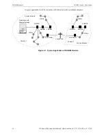
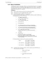
Step 5. All telephone line connections are recommended to use surge suppression devices on the
circuit. Accepted manufacturers and models are DITEK, model 2MLPL110B or EDCO,
model PC2TEL. These devices must be mounted in their own enclosures to the
JNISCAB-5 with all connections run in conduit. The following illustration is a typical
installation block diagram.
Figure 4.7 Telephone Line Surge Suppression
•
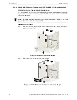
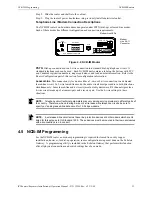
The DITEK and EDCO modules are identical in both installation and operation.
shows wiring terminations for up to 2-pairs of wires and is typical for both manufacturer's
models.
Figure 4.8 DITEK or EDCO Wiring Block
Step 6. Connect your Echelon network wires to the router connector labeled NETWORK.
Step 7. Plug the router’s transformer power supply into the router’s DC power connector.
3
2 wire tip/4 wire transmit tip
4
2 wire ring/4 wire transmit ring
5
4 wire receive ring (4-wire channels
only)
6
No Connection
Unprotected
Phone Line
Protected
Phone Line
Echelon
Network
Echelon
Network
Protected
Phone Line
NCB-IM
Surge
Suppressor
NCB-IM
Surge
Suppressor
9
7
5
3
1
10
8
6
4
2
Pair 2 Unprotected
Supply Wiring
Pair 1 Unprotected
Supply Wiring
Ground
Interconnect Keys
Pair 2 Out to
Protected Equipment
Ground
Pair 1 Out to
Protected Equipment


