background image

288591-BIM-C-0408

4

Johnson Controls Unitary Products

Location

Use the following guidelines to select a suitable location for 
these units.

1.

Unit is designed for outdoor installation only.

2.

Condenser must have an unlimited supply of air. Where a 
choice of location is possible, position unit on either north 
or east side of building.

3.

For ground level installation, a level pad or slab should be 
used. The thickness and size of the pad or slab used 
should meet local codes and unit weight. Do not tie the 
slab to the building foundation.

4.

For roof top installation, be sure the structure can support 
the weight of the unit plus any field installed components. 
Unit must be installed on a level roof curb or appropriate 
angle iron frame providing adequate support under the 
compressor/condenser section.

5.

Maintain level tolerance of unit to 1/8” maximum.

Clearances

All units require certain clearances for proper operation and 
service. Refer to Table 4 for the clearances required for 
construction, servicing and proper unit operation.

Rigging And Handling

Exercise care when moving the unit. Do not remove any 
packaging until the unit is near the place of installation. Rig the 
unit by attaching chain or cable slings to the lifting holes 
provided in the base rails. Spreader bars, whose length 
exceeds the largest dimension across the unit, 

MUST

 be used 

across the top of the unit.

Units may be moved or lifted with a forklift. Slotted openings in 
the base rails are provided for this purpose.

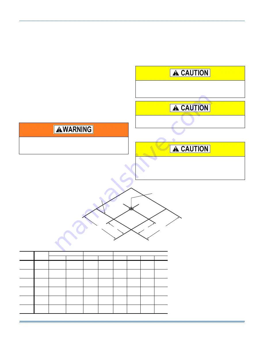
Figure 2: Unit 4 Point Load Weight

Do not permit overhanging structures or shrubs to 
obstruct condenser air discharge outlet, combustion air 
inlet or vent outlets.

If a unit is to be installed on a roof curb other than a 
UPG roof curb, gasketing must be applied to all surfaces 
that come in contact with the unit underside.

Before lifting, make sure the unit weight is distributed 
equally on the rigging cables so it will lift evenly.

All panels must be secured in place when the unit is 
lifted.

The condenser coils should be protected from rigging 
cable damage with plywood or other suitable material.

X

CENTER OF 

GRAVITY

49-1/8

FRONT

OF 

UNIT

Y

47-1/4

"D"

"C"

"B"

"A"

Size

(Tons)

Model

Weight (lbs.)

Center of Gravity

4 Point Load Location (lbs.)

Shipping Operating

X

Y

A

B

C

D

024

(2.0)

DPX

360

355

22.25

25

96

84

81

93

030

(2.5)

DPX

395

390

22.25

25

106

92

89

102

036

(3.0)

DPX

405

400

22.25

25

109

95

92

105

042

(3.5)

DPX

415

410

22.25

25

111

97

94

108

048

(4.0)

DPX

445

440

22.25

25

120

104

101

115

060

(5.0)

DPY

465

460

22.25

25

125

109

105

121

Содержание DPX024

Страница 1: ...g Diagram 9 10 Control Board Speed Tap Location 18 11 R 410A Quick Reference Guide 24 General Models DPX and DPY units are factory assembled cooling units designed for outdoor installation on a roof top or a slab Field installed electric heater accessories are available to provide supplemental electric heat combined with electric cooling The units are completely assembled on rigid removable base r...

Страница 2: ...t not limited to building electrical and mechanical codes Before performing service or maintenance operations on unit turn off main power switch to unit Electrical shock could cause personal injury Improper installation adjustment alteration service or maintenance can cause injury or property damage Refer to this manual For assistance or additional information consult a qualified installer or serv...

Страница 3: ...t Drive Condenser Fan Motor Highly Efficient Enhanced Copper Tube Aluminum Fin Indoor Coil Highly Efficient Enhanced Copper Tube Aluminum Fin Outdoor Coil Decorative Protective Coil Guard ECM Direct Drive Blower Motor With Slide Out Blower Assembly Heavy Gauge Removable Base Rails High Efficiency Compressor Rigidly Mounted Long Lasting Powder Paint Finish Low Voltage Terminal Block High Voltage Te...

Страница 4: ...installation Rig the unit by attaching chain or cable slings to the lifting holes provided in the base rails Spreader bars whose length exceeds the largest dimension across the unit MUST be used across the top of the unit Units may be moved or lifted with a forklift Slotted openings in the base rails are provided for this purpose Figure 2 Unit 4 Point Load Weight Do not permit overhanging structur...

Страница 5: ...RN AIR OPENING SIDE SUPPLY AIR OPENING LOW VOLTAGE CONN 7 8 DIA KNOCKOUT HIGH VOLTAGE CONN 1 31 32 DIA KNOCKOUT HIGH VOLTAGE CONN 7 8 DIA KNOCKOUT A 3 3 4 1 1 2 2 1 2 2 1 2 2 3 8 4 1 2 49 1 8 28 1 4 28 1 4 47 1 4 17 1 4 17 1 4 22 1 4 22 1 4 Table 3 Unit Dimensions Front Unit Size Dimensions A 024 030 036 33 1 2 042 048 0601 1 DPY Models 41 1 2 Table 4 Unit Clearances Direction Distance in Directio...

Страница 6: ...NT 26 3 4 CONDENSATE DRAIN 3 4 NPTI LOW VOLTAGE CONN 7 8 DIA KNOCKOUT HIGH VOLTAGE CONN 1 31 32 x 7 8 KNOCKOUT 22 1 2 43 1 2 40 1 2 4 14 1 2 28 3 8 14 1 2 BACK 3 3 8 SIDE RETURN AIR OPENING 14 1 2 3 1 2 3 1 2 15 1 3 4 1 3 4 BOTTOM RETURN AIR OPENING 15 28 9 16 15 1 3 4 BOTTOM SUPPLY AIR OPENING CONDENSER COIL SIDE SUPPLY AIR OPENING ...

Страница 7: ... on the curb so the front of the unit is tight against the curb Filters Single phase units are shipped without a filter or filter racks It is the responsibility of the installer to secure a filter in the return air ductwork or install a Filter Frame Kit 1FF0114 A filter rack and high velocity filters are standard on three phase units Filters must always be used and must be kept clean When filters ...

Страница 8: ...ing the cabinet must be provided with mechanical strain relief A fused disconnect switch should be field provided for the unit If any of the wire supplied with the unit must be replaced replacement wire must be of the type shown on the wiring diagram Electrical line must be sized properly to carry the load Each unit must be wired with a separate branch circuit fed directly from the meter panel and...

Страница 9: ...1 2 4 3 None 18 3 25 2NH04500506 3 8 5 1 18 1 20 8 27 9 31 4 30 35 2NH04500706 5 6 7 5 2 27 1 31 3 39 2 44 4 40 45 2NH04501006 7 5 10 2 36 1 41 7 50 5 57 5 60 60 030 2 5 DPX 208 230 1 60 14 1 70 22 1 2 4 3 None 23 1 30 2NH04500506 3 8 5 1 18 1 20 8 27 9 31 4 35 35 2NH04500706 5 6 7 5 2 27 1 31 3 39 2 44 4 40 45 2NH04501006 7 5 10 2 36 1 41 7 50 5 57 5 60 60 2NH04501506 11 3 15 2 54 2 62 5 73 1 83 ...

Страница 10: ... 5 10 2 36 1 41 7 56 5 63 5 60 70 2NH04501506 11 3 15 2 54 2 62 5 79 1 89 5 80 90 2NH04502006 15 20 2 72 2 83 3 101 7 115 5 110 125 2NH04502506 18 8 25 2 90 3 104 2 124 2 141 6 125 150 208 230 3 60 17 6 123 28 1 7 9 1 None 32 8 40 2NH04501025 7 5 10 1 20 8 24 1 37 4 41 4 45 50 2NH04501525 11 3 15 1 31 3 36 1 50 5 56 5 60 60 2NH04502025 15 20 2 41 7 48 1 63 5 71 5 70 80 2NH04502525 18 8 25 2 52 1 6...

Страница 11: ...laced Interlaced Interlaced Interlaced Interlaced Refrigerant control TX Valve TX Valve TX Valve TX Valve TX Valve TX Valve CONDENSER FAN DATA Fan diameter Inch 22 22 22 22 22 22 Type Prop Prop Prop Prop Prop Prop Drive type Direct Direct Direct Direct Direct Direct No speeds 1 1 1 1 1 1 Number of motors 1 1 1 1 1 1 Motor HP each 1 4 1 4 1 4 1 4 1 3 1 3 RPM 850 850 850 1100 1100 1100 Nominal total...

Страница 12: ...0 120 140 160 180 W1 HEAT D 800 99 117 137 156 030 2 5 DPX Cool Low Y1 COOL A 670 61 78 95 113 130 148 166 184 201 Y1 COOL B 620 54 70 87 104 121 138 156 173 191 Y1 COOL C 720 70 88 106 124 142 160 178 197 215 Y1 COOL D 770 81 99 118 136 155 174 193 213 232 High Y1 Y2 COOL A 1000 159 179 200 222 246 270 296 323 350 Y1 Y2 COOL B 925 129 148 169 190 211 233 256 280 304 Y1 Y2 COOL C 1075 194 214 236 ...

Страница 13: ...OOL C 525 47 63 79 95 112 129 146 164 182 Y1 COOL D 675 71 88 106 124 142 161 179 198 216 High Y1 Y2 COOL A 800 99 117 137 156 176 196 217 237 258 Y1 Y2 COOL B 600 57 74 91 108 126 143 161 179 197 Y1 Y2 COOL C 700 76 94 112 130 148 167 186 205 224 Y1 Y2 COOL D 900 126 146 166 187 208 231 253 277 300 Heat W1 HEAT A 800 99 117 137 156 W1 HEAT B 720 80 98 116 135 W1 HEAT C 880 120 140 160 180 W1 HEAT...

Страница 14: ...435 463 485 505 Y1 COOL B 1110 205 258 304 345 381 410 434 451 465 Y1 COOL C 1210 255 301 344 384 420 454 483 509 533 Y1 COOL D 1270 286 329 371 410 448 483 516 547 576 High Y1 Y2 COOL A 1750 559 608 658 710 762 815 870 925 981 Y1 Y2 COOL B 1650 498 542 588 634 683 732 783 835 888 Y1 Y2 COOL C 1800 590 643 696 750 805 860 916 973 1030 Y1 Y2 COOL D 1900 654 715 775 836 895 955 1013 1072 Heat W1 HEA...

Страница 15: ...m Supply Air CFM Heater kW 5 0 7 5 10 0 15 0 20 0 25 0 024 2 0 DPX 208 230 1 60 630 630 800 030 2 5 DPX 208 230 1 60 630 630 800 800 036 3 0 DPX 208 230 1 60 1070 1070 1070 1070 208 230 3 60 1070 1070 1070 1070 460 3 60 1070 1070 1070 1070 042 3 5 DPX 208 230 1 60 1225 1225 1225 1225 208 230 3 60 1225 1225 1225 1225 460 3 60 1225 1225 1225 1225 048 4 0 DPX 208 230 1 60 1200 1430 1430 1430 208 230 ...

Страница 16: ... 16 5 17 0 110 12 1 12 3 12 6 12 9 13 2 13 4 13 7 14 7 15 8 16 3 16 8 115 11 9 12 2 12 5 12 7 13 0 13 2 13 5 14 5 15 6 16 1 16 6 Table 15 DPX036 Superheat Charging Outdoor Temp F Superheat at Compressor Suction F Airflow 1200 CFM Indoor Wet Bulb Temp F 55 57 59 61 63 65 67 69 71 73 75 65 18 2 18 5 18 8 19 1 19 4 19 7 20 0 20 6 21 3 21 6 21 9 70 18 7 18 9 19 1 19 3 19 6 19 8 20 0 20 6 21 1 21 4 21 ...

Страница 17: ...CFM The airflow required for Electric Heat may be different than for cooling Refer to Table 10 for the minimum required CFM for the electric heater installed Find the desired airflow in Tables 7 and 8 Set the Heat Jumper on the CFM selection board to tap shown Table 17 DPX048 Superheat Charging Outdoor Temp F Superheat at Compressor Suction F Airflow 1600 CFM Indoor Wet Bulb Temp F 55 57 59 61 63 ...

Страница 18: ...e fan switch on the thermostat is in the ON position the 24 volts at G signals the ECM motor controller to operate the blower at 75 of the rated airflow If the fan switch on the thermostat is in the AUTO position the blower operates only when there is a call for heating by the thermostat 2 For units equipped with supplementary electric heat 24 volts at W sends 24 volts to W2 on the fan control boa...

Страница 19: ...EAT INSTANT ON HEATER BANK 2 ELEC HEAT 10 SEC DELAY ON HEATER BANK 3 ELEC HEAT 20 SEC DELAY ON OFF HEATER BANK 3 ELEC HEAT INSTANT OFF HEATER BANK 2 ELEC HEAT 1 2 SEC DELAY OFF HEATER BANK 1 ELEC HEAT 1 SEC DELAY OFF BLOWER 60 SEC DELAY OFF Table 21 Thermostat Signals Three Phase Units Signal State Board Function G ON BLOWER INSTANT ON AT 75 RATED AIRFLOW OFF BLOWER INSTANT OFF G Y1 ON BLOWER INST...

Страница 20: ...r suitable means If water is used to clean the coil be sure that the power to the unit is shut off prior to cleaning Troubleshooting Prior to any of the following maintenance procedures shut off all power to the unit to avoid personal injury Exercise care when cleaning the coil so that the coil fins are not damaged Do not permit the hot condenser air discharge to be obstructed by overhanging struc...

Страница 21: ...288591 BIM C 0408 Johnson Controls Unitary Products 21 Typical Wiring Diagrams Typical DPX024 048 DPY060 Cooling Only 208 230 1 60 volt Wiring Diagram ...

Страница 22: ...288591 BIM C 0408 22 Johnson Controls Unitary Products Typical DPX036 048 DPY060 Cooling Only 208 230 3 60 volt Wiring Diagram ...

Страница 23: ...288591 BIM C 0408 Johnson Controls Unitary Products 23 Typical DPX036 048 DPY060 Cooling Only 460 3 60 volt Wiring Diagram ...

Страница 24: ...harging cylinders and recovery equipment must be dedicated for use on R 410A systems only Manifold sets must be at least 700 psig high side and 180 psig low side with 550 psig retard All hoses must have a service pressure rating of 800 psig Leak detectors must be designed to detect HFC refrigerants Systems must be charged with liquid refrigerant Use a commercial type metering device in the manifol...

Отзывы: