


6052931-UAI-A-0121
Johnson Controls Ducted Systems
3
6.
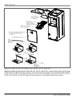
Install the electric heat kit as follows:
a.
Position and insert the electric heat kit into the opening
in the air handler unit.
b.
Align the mount holes and fasten the electric heat kit to
the air handler unit with four duct cover screws.
7.
Remove and discard the air handler power connection wir-
ing that is for use without electric heat (the connector con-
taining only the red and black wires) from the 6-pin
connector.
8.
Connect the 6-pin socket connector of the electric heat kit
to the control/power 6-pin connector in the air handler. The
end terminals are D-shaped to ensure polarization of the
connector.
9.
Mark an X in the appropriate box on the indoor unit rating
plate for the particular electric heat kit installed.
10. Refer to the unit rating plate for the minimum blower speed
required for the electric heat kit model installed, and set the
blower speed accordingly.
CAUTION
To prevent damage, carefully pass the accessory heating ele-
ment through the rectangular opening in the discharge duct.
Element mounting plate must be secured with four screws.
!
WARNING
Verify edges of foil faced insulation are not in contact with any
exposed electrical connections.
NOTICE
All wiring must comply with local and National Electrical Code
requirements. Read and heed all unit caution labels.
NOTICE
An optional service disconnect cover can be applied to seal/
protect the Service Disconnects (S1-02435672000).
!
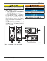
Figure 2:
Typical electric heat kit installations - air handler
UPFLOW
HORIZONTAL RIGHT
HORIZONTAL LEFT
HEAT
HEA
T
HEA
T
DOWNFLOW
HEAT
A0330-001


