background image

689670-BIM-A-0311

Johnson Controls Unitary Products

19

Thermostat Wiring

The thermostat should be located on an inside wall 
approximately 56 inch above the floor where it will not be 
subject to drafts, sun exposure or heat from electrical fixtures or 
appliances. Follow the manufacturer's instructions enclosed 
with thermostat for general installation procedure. Seven (7) 
color-coded, insulated wires should be used to connect the 
thermostat to the unit. Refer to Table 7 for control wire sizing 
and maximum length.

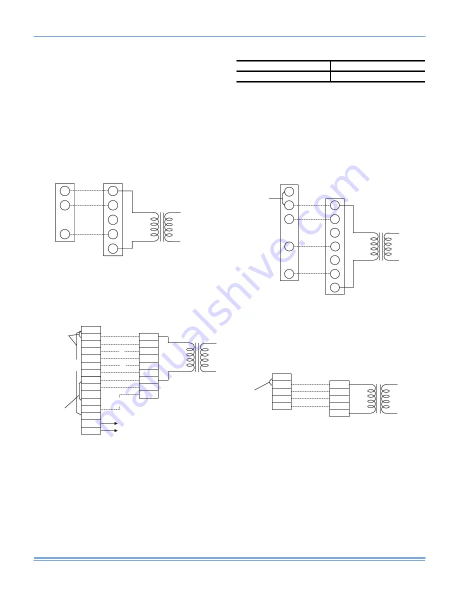
Typical Control Wiring Detail

Figure 21: Typical Control Wiring

Table 7:

Control Wire Sizes

Wire Size

Maximum Length

1

18 AWG

150 Feet

1. From the unit to the thermostat and back to the unit.

RC

RH

Y1

Y2

W1

W2

G

LED 1

LED 2

COM

A1

A2

T

T

B

R

Y1

Y2

G

C

X

OCC

W2

W1

THERMOSTAT

1

TERMINALS

UNIT TERMINAL

STRIP TB1

24 VOLT

TRANSFORMER

TO REMOTE SENSOR

2TH040702224 IF USED

NOT
USED

ADD

JUMPER

ADD

JUMPER

4

4

3

2

1

 ELECTRONIC PROGRAMMABLE THERMOSTAT 2ET04700224 (INCLUDES SUBBASE).

2

 SECOND STAGE COOLING IS NOT REQUIRED ON UNITS LESS ECONOMIZER.

3

 SECOND STAGE HEATING IS ONLY REQUIRED ON UNITS WITH A TWO STAGE

   ELECTRIC HEATER OR 2 STAGE GAS HEAT.

4

REMOVE JUMPER J2 FROM TERMINALS 4 AND 9 ON JUMPER PLUG CONNECTOR
P6 ON UNITS WITH ECONOMIZER. TERMINALS A1 AND A2 PROVIDE A RELAY
OUT-PUT TO CLOSE THE OUTDOOR ECONOMIZER DAMPERS WHEN THE
THERMOSTAT SWITCHES TO THE SET-BACK POSITION.

COOLING / HEATING (ELECTRONIC THERMOSTAT)

MULTI STAGE

RH

RC

Y

W

G

R

Y1

W1

C

G

ADD

JUMPER

THERMOSTAT

1

TERMINALS

UNIT TERMINAL

STRIP TB1

24 VOLT

TRANSFORMER

1

ELECTRONIC PROGRAMMABLE THERMOSTAT 2ET07701024 (INCLUDES SUBBASE).
TO CONTROL THE ECONOMIZER ON SECOND STAGE COOLING, USE THERMOSTAT
2TH04700224.

COOLING / HEATING (ELECTRONIC THERMOSTAT)

SINGLE STAGE

RV

YC

GF

R

Y1

C

Y2

THERMOSTAT

1

TERMINALS

UNIT TERMINAL

STRIP TB1

24 VOLT

TRANSFORMER

1

24 VOLT THERMOSTAT 2TH07701024. TO CONTROL THE ECONOMIZER
ON SECOND STAGE COOLING, USE THE THERMOSTAT 2TH0401224.

G

COOLING ONLY (24 VOLT THERMOSTAT)

RC

Y

R

Y1

Y2

W1

W

W2

G

C

G

RH

THERMOSTAT

TERMINALS

UNIT TERMINAL

STRIP TB1

24 VOLT

TRANSFORMER

ADD

JUMPER

1

24 VOLT THERMOSTAT 2ET07701024. TO CONTROL THE ECONOMIZER ON THE SECOND
STAGE COOLING OR TO HAVE AN ELECTRIC HEAT ACCESSORY WITH TWO STAGES OF
HEAT, USE THERMOSTAT 2TH0471024.

1

COOLING / HEATING (24 VOLT THERMOSTAT)

Содержание 20 J ZJ Series

Страница 1: ...rflow Performance Side Duct Application 36 16 Airflow Performance Bottom Duct Application 37 17 RPM Selection 38 18 Indoor Blower Specifications 38 19 Power Exhaust Specifications 38 20 Motor Sheave Datum Diameters 40 21 Additional Static Resistance 41 22 Electric Heat Limit Setting 44 23 Electric Heat Anticipator Setpoints 45 24 Gas Heat Anticipator Setpoints 47 25 Gas Rate Cubic Feet Per Hour 49...

Страница 2: ...autions and codes including ANSI Z223 1 or CSA B149 1 latest edition Improper installation may create a condition where the operation of the product could cause personal injury or property damage Improper installation adjustment alteration service or maintenance can cause injury or property damage Refer to this manual for assistance or for additional information consult a qualified contractor inst...

Страница 3: ...mbustible material and may be installed directly on combustible flooring or in the U S on wood flooring or Class A Class B or Class C roof covering materials 4 For use with natural gas convertible to LP with kit This product must be installed in strict compliance with the enclosed installation instructions and any applicable local state and national codes including but not limited to building elec...

Страница 4: ...r Simplicity IntelliComfort Controller w Simplicity Linc 2 Pleated filters BAS Ready Unit with Economizer Shipping Bag Any Combination of Additional Options that Don t Have an Option Code Pre assigned AA None AB Phase Monitor AC Coil Guard AD Dirty Filter Switch AE Phase Monitor Coil Guard AF Phase Monitor Dirty Filter Switch AG Coil Guard Dirty Filter Switch AH Phase Monitor Coil Guard Dirty Filt...

Страница 5: ... Bracket 2 Turn each bracket toward the ground and the protective plywood covering will drop to the ground 3 Remove the condenser coil external protective covering prior to operation 4 Remove the toolless doorknobs and instruction packet prior to installation Figure 2 Condenser Covering Figure 3 Compressor Section 5 If a factory option convenience outlet is installed the weatherproof outlet cover ...

Страница 6: ...n this product is applied in a comfort cooling application for people An economizer is typically included in this type of application When applying this product for process cooling applications computer rooms switchgear etc please reference applications bulletin AE 011 07 or call the applications department for Unitary Products 1 877 UPG SERV for guidance Additional accessories may be needed for s...

Страница 7: ...ng until the unit is near the place of installation Rig the unit by attaching chain or cable slings to the lifting holes provided in the base rails Spreader bars whose length exceeds the largest dimension across the unit MUST be used across the top of the unit Units may be moved or lifted with a forklift Slotted openings in the base rails are provided for this purpose LENGTH OF FORKS MUST BE A MIN...

Страница 8: ...l Weight lbs Center of Gravity 4 Point Load Location lbs 6 Point Load Location lbs Shipping Operating X Y A B C D A B C D E F A3 3 ZU 728 723 40 26 175 143 182 223 121 105 92 117 134 154 A4 4 ZU 768 763 40 26 185 151 192 235 128 111 97 124 141 162 A5 5 ZU 869 864 40 26 210 171 217 266 145 126 110 140 160 184 Table 3 ZU A3 thru A5 Unit Accessory Weights Unit Accessory Weight lbs Shipping Operating ...

Страница 9: ...son Controls Unitary Products 9 Figure 8 ZU A3 thru A4 Physical Dimensions Ø 25 31 59 00 15 51 29 75 59 LEFT 11 3 8 21 3 16 89 27 5 16 4 3 16 FRONT See detail A for gas inlet A See detail B for drain location B C D E F 29 52 ...

Страница 10: ...on Controls Unitary Products Figure 9 ZU A5 Physical Dimensions Ø 24 47 TYP 2 PL 15 38 15 38 59 00 15 25 29 69 59 LEFT 11 3 8 21 3 16 89 27 5 16 4 3 16 FRONT See detail A for gas inlet A See detail B for drain location B C D E F ...

Страница 11: ... 16 15 3 16 6 3 16 42 CABINET Ø 3 126 Ø 2 000 3 184 4 727 7 705 14 594 Gas Pipe Inlet Gas Exhaust Vent 5 3 8 3 4 FPT Table 5 ZU A3 thru A5 Unit Clearances Direction Distance in Direction Distance in Top1 1 Units must be installed outdoors Over hanging structure or shrubs should not obscure condenser air discharge outlet 72 Right 12 Front 36 Left 36 Rear 36 Bottom2 2 Units may be installed on combu...

Страница 12: ...nit Bottom Duct Openings Bottom condensate drain Bottom gas supply entry FRONT RETURN AIR SUPPLY AIR RIGHT LEFT 20 1 8 19 1 8 17 1 8 6 13 16 6 13 16 32 11 16 14 1 2 16 3 8 18 1 16 25 9 16 12 5 16 27 1 2 24 21 18 89 Ø 2 469 3X Ø 0 875 Bottom power control and convenience outlet wiring entry ...

Страница 13: ... Cover Power Entry Ø 2 1 2 Control Entry Ø 7 8 Power Entry Ø 2 1 2 Convenience Outlet Cover Convenience Outlet Power Entry Ø 7 8 FRONT Dot Plugs 5 5 32 31 11 16 2 31 32 18 1 4 Return Air Supply Air A B C D Table 6 Side Duct Dimensions Unit Model Number Dimension in A B C D ZU A3 27 3 4 12 1 16 27 1 2 16 ZU A4 27 3 4 12 1 16 27 1 2 16 ZU A5 27 3 4 12 1 16 27 1 2 16 ...

Страница 14: ...Products Figure 13 ZU A3 thru A5 Unit Left Duct Opening Figure 14 ZU A3 thru A5 Roof Curb 4 5 16 30 3 8 8 or 14 50 1 2 30 20 20 80 5 8 6 2 TYP INSULATED DECK UNDER COMPRESSOR SECTION INSULATED DECK UNDER CONDENSER SECTION FRONT RIGHT SUPPLY RETURN ...

Страница 15: ... over the bottom of the unit For bottom duct application no duct cover changes are necessary For side duct application remove the side duct covers and install over the bottom duct openings The panels removed from the side duct connections are designed to be reused by securing each panel to its respective downflow opening But keep in mind that the supply panel is installed with the painted surface ...

Страница 16: ...s to avoid exposure of the oil to the atmosphere POE polyolester compressor lubricants are known to cause long term damage to some synthetic roofing materials Procedures which risk oil leakage include but are not limited to compressor replacement repairing refrigerant leaks replacing refrigerant components such as filter drier pressure switch metering device or coil Units are shipped with compress...

Страница 17: ...the replaced wire A disconnect must be utilized for these units Factory installed disconnects are available If installing a disconnect field supplied or UP supplied accessory refer to Figure 4 for the recommended mounting location NOTE Since not all local codes allow the mounting of a disconnect on the unit please confirm compliance with local code before mounting a disconnect on the unit Electric...

Страница 18: ... the unit nameplate Refer to Electrical Data Table 8 to size power wiring fuses and disconnect switch Power wiring is brought into the unit through the side of the unit or the basepan inside the curb Figure 20 Field Wiring Disconnect THREE PHASE POWER SUPPLY FACTORY OR FIELD SUPPLIED DISCONNECT GROUND LUG TERMINAL BLOCK TB1 ...

Страница 19: ...OMIZER 3 SECOND STAGE HEATING IS ONLY REQUIRED ON UNITS WITH A TWO STAGE ELECTRIC HEATER OR 2 STAGE GAS HEAT 4 REMOVE JUMPER J2 FROM TERMINALS 4 AND 9 ON JUMPER PLUG CONNECTOR P6 ON UNITS WITH ECONOMIZER TERMINALS A1 AND A2 PROVIDE A RELAY OUT PUT TO CLOSE THE OUTDOOR ECONOMIZER DAMPERS WHEN THE THERMOSTAT SWITCHES TO THE SET BACK POSITION COOLING HEATING ELECTRONIC THERMOSTAT MULTI STAGE RH RC Y ...

Страница 20: ... 35 E06 4 5 1 12 5 23 1 30 30 35 E08 6 8 1 18 9 31 1 38 35 40 E15 11 3 2 31 4 46 7 53 6 50 60 E20 15 2 41 6 59 5 66 4 60 70 230 11 2 88 17 5 1 5 6 0 5 5 0 0 None 21 7 27 30 35 E06 6 1 14 4 25 5 32 4 30 35 E08 9 1 21 7 34 6 41 4 35 45 E15 15 2 36 1 52 6 59 5 60 60 E20 20 2 48 1 67 6 74 5 70 80 460 5 6 44 8 0 0 8 3 0 2 2 0 0 None 10 8 13 15 15 E06 6 1 7 2 12 8 15 5 15 20 E08 9 1 10 8 17 3 20 20 20 E...

Страница 21: ...12 5 23 1 30 30 35 E08 6 8 1 18 9 31 1 38 35 40 E15 11 3 2 31 4 46 7 53 6 50 60 E20 15 2 41 6 59 5 66 4 60 70 230 11 2 88 17 5 1 5 6 0 5 5 0 0 None 21 5 27 30 35 E06 6 1 14 4 25 5 32 4 30 35 E08 9 1 21 7 34 6 41 4 35 45 E15 15 2 36 1 52 6 59 5 60 60 E20 20 2 48 1 67 6 74 5 70 80 460 5 6 44 8 0 0 8 3 0 2 2 0 0 None 10 8 13 15 15 E06 6 1 7 2 12 8 15 5 15 20 E08 9 1 10 8 17 3 20 20 20 E15 15 2 18 0 2...

Страница 22: ... 5 1 12 5 35 6 42 5 40 45 E08 6 8 1 18 9 43 6 50 5 45 60 E15 11 3 2 31 4 59 2 66 1 60 70 E20 15 2 41 6 72 78 9 80 80 230 11 2 88 17 5 1 5 6 0 5 5 10 0 None 31 5 37 40 45 E06 6 1 14 4 38 44 9 40 45 E08 9 1 21 7 47 1 53 9 50 60 E15 15 2 36 1 65 1 72 70 80 E20 20 2 48 1 80 1 87 90 90 460 5 6 44 8 0 0 8 3 0 2 2 5 0 None 15 8 18 20 20 E06 6 1 7 2 19 21 8 20 25 E08 9 1 10 8 23 5 26 3 25 30 E15 15 2 18 0...

Страница 23: ...5 1 12 5 35 6 42 5 40 45 E08 6 8 1 18 9 43 6 50 5 45 60 E15 11 3 2 31 4 59 2 66 1 60 70 E20 15 2 41 6 72 78 9 80 80 230 11 2 88 17 5 1 5 6 0 5 5 10 0 None 31 5 37 40 45 E06 6 1 14 4 38 44 9 40 45 E08 9 1 21 7 47 1 53 9 50 60 E15 15 2 36 1 65 1 72 70 80 E20 20 2 48 1 80 1 87 90 90 460 5 6 44 8 0 0 8 3 0 2 2 5 0 None 15 8 18 20 20 E06 6 1 7 2 19 21 8 20 25 E08 9 1 10 8 23 5 26 3 25 30 E15 15 2 18 0 ...

Страница 24: ...teady state efficiency 81 5 81 81 81 5 81 81 81 81 80 5 No burners 4 4 6 4 4 6 4 6 8 No stages 1 1 1 1 1 1 1 1 1 Temperature Rise Range ºF 20 50 F 25 65 F 50 80 F 20 50 F 25 65 F 40 70 F 25 65 F 35 65 F 45 75 F Gas Limit Setting ºF 235 F 200 F 255 F 235 F 200 F 255 F 200 F 245 F 240 F Gas piping connection in 3 4 3 4 3 4 3 4 3 4 3 4 3 4 3 4 3 4 DIMENSIONS inches Length 89 89 89 Width 59 59 59 Heig...

Страница 25: ...al Motor Sheave 1VM34 1VL44 1VM34 1VL44 1VL40 1VP56 Blower Sheave AK69 AK69 AK56 AK56 AK61 AK74 Belt A47 A47 A47 A47 A47 A51 Motor HP each 1 1 2 1 1 2 1 1 2 1 1 2 1 1 2 2 RPM 1725 1725 1725 1725 1725 1725 Frame size 56 56 56 56 56 56 FILTERS Quantity Size 4 24 x 16 x 2 1 2 4 24 x 16 x 2 1 2 4 24 x 16 x 2 1 2 4 24 x 16 x 4 3 4 24 x 16 x 4 3 4 24 x 16 x 4 3 1 2 In Throwaway Standard MERV Minimum Eff...

Страница 26: ...iency 81 5 81 81 81 5 81 81 81 81 80 5 No burners 4 4 6 4 4 6 4 6 8 No stages 21 22 22 21 22 22 22 22 22 Temperature Rise Range ºF 20 50 F 25 65 F 50 80 F 20 50 F 25 65 F 40 70 F 25 65 F 35 65 F 45 75 F Gas Limit Setting ºF 235 F 200 F 255 F 235 F 200 F 255 F 200 F 245 F 240 F Gas piping connection in 3 4 3 4 3 4 3 4 3 4 3 4 3 4 3 4 3 4 DIMENSIONS inches Length 89 89 89 Width 59 59 59 Height 42 42...

Страница 27: ... of motors 1 1 2 Motor HP each 1 3 1 3 1 3 No speeds 1 1 1 RPM 850 850 850 Nominal total CFM 3300 3700 6700 BELT DRIVE EVAP FAN DATA Quantity 1 1 1 Fan Size Inch 12 x 9 12 x 9 12 x 9 Type Centrifugal Centrifugal Centrifugal Motor Sheave 1VM34 1VL44 1VM34 1VL44 1VL40 1VP56 Blower Sheave AK69 AK69 AK56 AK56 AK61 AK74 Belt A47 A47 A47 A47 A47 A51 Motor HP each 1 1 2 1 1 2 1 1 2 1 1 2 1 1 2 2 RPM 1725...

Страница 28: ...r with locality The value should be checked with the local gas utility Figure 22 Side Entry Gas Piping Figure 23 Bottom Entry Gas Piping NOTE Maximum capacity of pipe in cubic feet of gas per hour based upon a pressure drop of 0 3 inch W C and 0 6 specific gravity gas NOTE There may be a local gas utility requirement specifying a minimum diameter for gas piping All units require a 3 4 inch pipe co...

Страница 29: ...mbers 1NP0454 or 1NP0455 All LP gas equipment must conform to the safety standards of the National Fire Protection Association Table 12 Gas Heat Minimum Supply Air Size Tons Model Heat Size Supply Air CFM Heating Min Max A3 3 ZU A06 N06 890 2220 A08 N08 915 2370 A11 N11 1130 1800 A4 4 ZU A06 N06 890 2220 A08 N08 915 2370 A11 N11 1290 2250 A5 5 ZU A08 N08 915 2370 A11 N11 1380 2570 A16 N16 1580 263...

Страница 30: ...rding to NFPA 72 requirements and cleaned at least once a year For specific troubleshooting and maintenance procedures please refer to the smoke detector s installation instructions which accompanies the unit Motorized Outdoor Damper The Motorized Outdoor Damper can be a factory installed option or a field installed accessory If factory installed refer to the instructions included with the outdoor...

Страница 31: ...Adjusting screw located on the damper control module counterclockwise until the desired minimum damper position has been attained Enthalpy Set Point Adjustment The enthalpy set point may now be set by selecting the desired set point shown in the Enthalpy Set Point Adjustment Figure 24 Adjust as follows For a single enthalpy operation carefully turn the set point adjusting screw found on the damper...

Страница 32: ...ed disconnect to obtain proper rotation Scroll compressors operate in only one direction If the scroll is drawing low amperage has similar suction and discharge pressures or producing a high noise level the scroll is misphased HIGH LIMIT CURVE W7212 N1 N P1 P EXH Set EXH Min Pos IAQ Max IAQ IAQ Min Free Cool T T1 AQ1 AQ SO SO SR SR A B C D TR TR1 24 Vac HOT 24 Vac COM EF EF1 2 3 4 5 1 Exhaust Air ...

Страница 33: ...less static pressure will be generated and less power will be required than a similar application at sea level Air density correction factors are shown in Table 14 and Figure 27 Scroll compressors require proper rotation to operate correctly Units are properly phased at the factory Do not change the internal wiring to make the blower condenser fans or compressor rotate correctly Table 13 Supply Ai...

Страница 34: ...given is at an elevation of 5 000 ft The first step is to convert this static pressure to equivalent sea level conditions Sea level static pressure 1 5 832 1 80 Enter the blower table at 6000 sCFM and static pressure of 1 8 The rpm listed will be the same rpm needed at 5 000 ft Suppose that the corresponding BHP listed in the table is 3 2 This value must be corrected for elevation BHP at 5 000 ft ...

Страница 35: ...s the maximum continuous BHP rating of the 1 5 HP motor The 2 HP motor is required 6 1230 RPM is within the range of the 2 HP drives 7 Using the 2 HP motor and drive 5 turns open will achieve 1230 RPM Airflow Performance Example Supply Air Blower Performance Air Flow CFM Available External Static Pressure IWG 0 2 0 4 0 6 0 8 1 0 1 2 1 4 1 6 1 8 2 0 RPM BHP RPM BHP RPM BHP RPM BHP RPM BHP RPM BHP R...

Страница 36: ... 0 81 1044 0 91 1106 1 01 1168 1 10 1231 1 18 1500 673 0 43 741 0 48 807 0 56 872 0 65 936 0 75 999 0 85 1061 0 96 1124 1 06 1186 1 15 1249 1 22 1600 691 0 48 759 0 54 825 0 61 890 0 70 954 0 80 1017 0 90 1079 1 01 1141 1 11 1204 1 20 1267 1 27 1700 709 0 54 777 0 59 843 0 67 908 0 76 972 0 86 1035 0 96 1097 1 07 1160 1 17 1222 1 26 1285 1 33 1800 728 0 60 796 0 66 862 0 73 927 0 82 991 0 92 1053 ...

Страница 37: ...75 1009 0 85 1071 0 94 1130 1 03 1187 1 12 1240 1 21 1500 697 0 42 763 0 51 830 0 61 896 0 71 961 0 80 1025 0 90 1087 0 99 1146 1 08 1203 1 17 1256 1 26 1600 714 0 47 780 0 57 846 0 66 913 0 76 978 0 86 1042 0 95 1103 1 04 1163 1 14 1220 1 22 1273 1 31 1700 732 0 53 798 0 63 864 0 73 930 0 82 996 0 92 1059 1 01 1121 1 10 1181 1 20 1237 1 29 1291 1 37 1800 751 0 60 817 0 70 883 0 79 950 0 89 1015 0...

Страница 38: ...ws after 10 12 hrs run time is recommended Table 17 RPM Selection Size Tons Model HP Max BHP Motor Sheave Blower Sheave 6 Turns Open 5 Turns Open 4 Turns Open 3 Turns Open 2 Turns Open 1 Turn Open Fully Closed A3 3 ZU 1 5 1 5 1VM34 AK69 N A 531 584 637 690 743 796 1 5 1 5 1VL44 AK69 N A 796 849 902 955 1008 1062 A4 4 ZU 1 5 1 5 1VM34 AK56 N A 663 730 796 863 929 995 1 5 1 5 1VL44 AK56 N A 995 1062...

Страница 39: ... variable motor sheave is open 5 Select the correct blower performance table for the unit from Tables 15 and 16 Tables are presented for side and downflow configuration 6 Determine the unit Measured CFM from the Blower Performance Table External Static Pressure and the number of turns the variable motor sheave is open 7 To adjust Measured CFM to Required CFM see SUPPLY AIR DRIVE ADJUSTMENT 8 After...

Страница 40: ...in blower speed can result in substantial changes in static pressure and BHP BHP and AMP draw of the blower motor will increase by the cube of the blower speed Static pressure will increase by the square of the blower speed Only qualified personnel should make blower speed changes strictly adhering to the fan laws Table 20 Motor Sheave Datum Diameters 1VM34x7 8 1 1 2 HP Motor 1VL44x7 8 1 1 2 HP Mo...

Страница 41: ... 04 0 00 0 04 0 01 0 01 0 01 0 02 0 02 0 02 1300 0 03 0 01 0 05 0 01 0 01 0 01 0 03 0 03 0 03 1400 0 03 0 03 0 07 0 02 0 02 0 02 0 03 0 03 0 03 1500 0 03 0 04 0 08 0 02 0 02 0 02 0 04 0 04 0 04 1600 0 02 0 06 0 09 0 02 0 02 0 02 0 04 0 04 0 04 1700 0 02 0 07 0 10 0 03 0 03 0 03 0 05 0 05 0 05 1800 0 01 0 08 0 11 0 03 0 03 0 03 0 05 0 05 0 05 1900 0 01 0 10 0 13 0 04 0 04 0 04 0 06 0 06 0 06 2000 0...

Страница 42: ...nomizer With Single Enthalpy Sensor When the room thermostat calls for cooling the low voltage control circuit from R to G and Y1 is completed The UCB energizes the blower motor if the fan switch on the room thermostat is set in the AUTO position and drives the economizer dampers from fully closed to their minimum position If the enthalpy of the outdoor air is below the setpoint of the enthalpy co...

Страница 43: ... pair of terminals connected to a temperature activated switch set at 45ºF When the low ambient switch is closed and the thermostat is calling for cooling the UCB will operate in the low ambient mode Low ambient mode operates the compressors in this manner 10 minutes on 5 minutes off The indoor blower is operated throughout the cycle The 5 minute off period is necessary to defrost the indoor coil ...

Страница 44: ...zed This limit is monitored regardless of unit operation status i e the limit is monitored at all times If the temperature limit opens three times within one hour it will lock on the indoor blower motor and a flash code is initiated See Table 27 Safety Controls The UCB monitors the temperature limit switch of electric heat units The control circuit includes the following safety controls Limit Swit...

Страница 45: ... begin After the flame stabilization period a loss of flame for 3 4 second will cause the GV to close and the retry operation to begin At the conclusion of the flame stabilization period the ICB will operate the gas heat in high fire for an additional 60 seconds for a total for 120 seconds of high fire operation After this 60 seconds the ICB will then use the call for the second stage of heat to c...

Страница 46: ...h of the fan off delay for heating During a call for heat if the UCB does not sense voltage at the GV for a continuous five minute period the UCB will initiate a flash code Table 27 The indoor blower motor will not be locked on while there is no GV voltage Safety Controls The UCB monitors the temperature limit switch of gas heat units The control circuit includes the following safety controls Limi...

Страница 47: ...om thermostat fan switch to on 5 Check indoor blower rotation If blower rotation is in the wrong direction Refer to Phasing Section in general information section Check blower drive belt tension 6 Check the unit supply air CFM 7 Measure evaporator fan motor s amp draw 8 Set the room thermostat fan switch to off 9 Turn unit electrical power off Operating Instructions 1 Turn unit electrical power on...

Страница 48: ...the number of seconds it takes for one revolution of the dial calculate the cubic feet of gas consumed per hour See example below 5 If necessary adjust the high pressure regulator as discussed in the section Manifold Gas Pressure Adjustment Be sure not to over fire the furnace on Second stage If in doubt it is better to leave the Second stage of the furnace slightly under fired Repeat Steps 1 5 To...

Страница 49: ...t 5 Set thermostat to call for second stage heat and start furnace 6 If necessary using a screwdriver turn the second stage adjustment screw adjacent to the HI marking on the valve clockwise to increase manifold pressure or counterclockwise to decrease manifold pressure Be sure not to over fire the unit on second stage 7 After the high manifold pressure has been checked adjust the thermostat to ca...

Страница 50: ...D SHUT OFF ALL POWER TO THE UNIT 1 Open the union fitting just upstream of the unit gas valve and downstream from the main manual shut off valve in the gas supply line 2 Remove the screws holding each end of the manifold to the manifold supports 3 Disconnect wiring to the gas valves and spark igniter s Remove the manifold gas valve assembly Orifices can now be inspected and or replaced To service ...

Страница 51: ...CB On a call for cooling the supply air blower motor is operating but the compressor is not the room thermostat fan switch is in the AUTO position 1 If installed check the position of the economizer blades If the blades are open the economizer is providing free cooling and the compressors will not immediately operate If both stages of cooling are requested simultaneously and the economizer provide...

Страница 52: ...e Mate N Lock plug and from the Mate N Lock plug to the Y1 ECON terminal If nothing is found the economizer actuator may have faulted and is failing to return the 24 volt call to the Y1 ECON terminal even though the economizer is not providing free cooling To test disconnect the Mate N Locks and jumper between the WHITE and YELLOW wires of the UCB s Mate N Lock plug If the compressor energizes the...

Страница 53: ...ltage at the motor leads If line voltage is present replace the draft motor 3 If line voltage is not present check for line voltage on the ignition control at the inducer terminal draft motor relay DMR or DMC contacts in the main control box and check to see if the DMR or DMC is pulled in The draft motor runs but the furnace does not light and the spark ignitor does not spark 1 Check for 24 volts ...

Страница 54: ...networked with other units this button is used to set the network address The first time the button is pressed within five seconds it scans the bus then assigns itself the first available address starts at 2 It then flashes that address one time Pressing the button two times within five seconds causes the control to flash its address Pressing the button three times within five seconds forces the c...

Страница 55: ...at Section 10 Flashes Compressors Locked Out On Low Outdoor Air Temperature1 11 Flashes Compressors Locked Out Because The Economizer Is Using Free Cooling1 13 Flashes Compressor Held Off Due To Low Voltage1 14 Flashes EEPROM Storage Failure Control Failure OFF No Power or Control Failure Table 28 Ignition Control Flash Codes Flashes Fault Conditions Check Steady On Control Failure Control Heartbe...

Отзывы: