JOHNSON CONTROLS
61
SECTION 4 – MAINTENANCE
FORM 100.50-NOM6
ISSUE DATE: 8/07/2017
4
Belt Replacement
Always replace belts as a set. Follow the steps below
to replace belts:
1. Release the tension on the belts by loosening the
adjusting nuts on the fan motor.
2. Remove old belts and recheck the sheave align-
ment with a straight edge.
3. Install the new belts on the sheaves.
Never place the belts on the sheaves by using a screw-
driver to pry the belt over the rim of the sheave. This
will permanently damage the belts.
Belt Tensioning
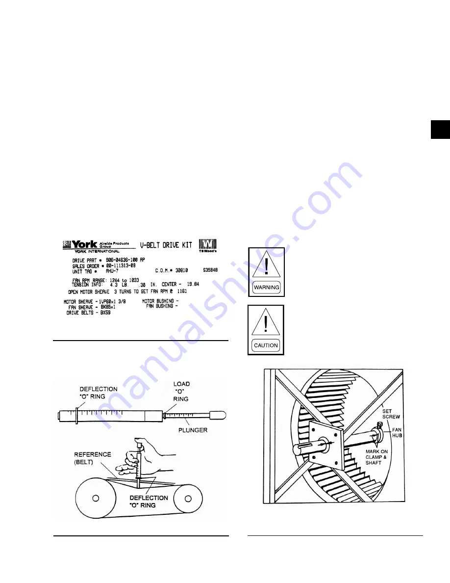
Belt tension information is included on the fan skid
data plate as shown in
. Sample
data plate shows 4.3 lbs pressure at .30 inches deflec-
tion.
00494vip
FIGURE 24 -
FAN DATA PLATE - BELT TENSION
A Browning Belt tension gauge is used in
LD06354
FIGURE 25 -
BELT TENSIONING GAUGE
Filter Drier Replacement
The filter/drier should be replaced any time work is
performed on the refrigerant circuit. The rooftop unit
comes with sealed type (non-replaceable) cores as
standard. If the unit is not equipped with the option-
al valve package (suction, discharge, and liquid line
valves), the refrigerant will need to be recovered with
a recovery machine to replace the filter/drier.
If the unit is equipped with a valve package, the unit
can be pumped down by closing the liquid line ball
valve (prior to the filter/drier) while the unit is run-
ning, initiating a unit pump-down. The unit will shut
off when the mechanical low-pressure switch opens.
When the unit shuts down, close the ball valve located
after the filter/drier and remove power from the unit
to prevent the unit from running. Once the filter/drier
core has been replaced, the filter/drier section should
be evacuated via the Schrader access valve located
next to the filter/drier prior to opening the ball valves
and restoring the unit to normal operation.
Never shut the discharge valve while the
unit is running. Doing so could cause a
rupture in the discharge line or compo-
nents, resulting in death or serious injury.
Never close the suction line ball valve with
the compressor running. Doing so will
cause the compressor to pump-down into
a vacuum and damage the compressor due
to internal arcing.
FIGURE 26 -
EXAMPLE OF FC FAN SHAFT/WHEEL
MARKING
LD06355
Содержание 050
Страница 112: ...JOHNSON CONTROLS 112 FORM 100 50 NOM6 ISSUE DATE 8 07 2017 SECTION 6 USER INTERFACE SENSOR READINGS LD13017 ...
Страница 113: ...JOHNSON CONTROLS 113 SECTION 6 USER INTERFACE FORM 100 50 NOM6 ISSUE DATE 8 07 2017 6 ECONOMIZER EXHAUST LD13018 ...
Страница 114: ...JOHNSON CONTROLS 114 FORM 100 50 NOM6 ISSUE DATE 8 07 2017 SECTION 6 USER INTERFACE FANS LD13019 ...
Страница 115: ...JOHNSON CONTROLS 115 SECTION 6 USER INTERFACE FORM 100 50 NOM6 ISSUE DATE 8 07 2017 6 COOLING SETUP LD13020 ...
Страница 116: ...JOHNSON CONTROLS 116 FORM 100 50 NOM6 ISSUE DATE 8 07 2017 SECTION 6 USER INTERFACE COOLING STATUS LD13021 ...
Страница 117: ...JOHNSON CONTROLS 117 SECTION 6 USER INTERFACE FORM 100 50 NOM6 ISSUE DATE 8 07 2017 6 HEATING SETUP LD13022 ...
Страница 118: ...JOHNSON CONTROLS 118 FORM 100 50 NOM6 ISSUE DATE 8 07 2017 SECTION 6 USER INTERFACE HEATING STATUS LD13023 ...
Страница 119: ...JOHNSON CONTROLS 119 SECTION 6 USER INTERFACE FORM 100 50 NOM6 ISSUE DATE 8 07 2017 6 SYSTEM OPTIONS LD13024 ...
Страница 120: ...JOHNSON CONTROLS 120 FORM 100 50 NOM6 ISSUE DATE 8 07 2017 SECTION 6 USER INTERFACE OUTPUTS STATUS LD13025 ...
Страница 122: ...JOHNSON CONTROLS 122 FORM 100 50 NOM6 ISSUE DATE 8 07 2017 SECTION 6 USER INTERFACE GRAPHIC LD13027 CLOCK LD13028 ...
Страница 125: ...JOHNSON CONTROLS 125 SECTION 6 USER INTERFACE FORM 100 50 NOM6 ISSUE DATE 8 07 2017 6 ALARMS LD13031 ...


