Installation, Operation & Maintenance Instructions
4
API PLAN 74
SEAL SYSTEMS
ATTENTION
Before commencing the start-up procedure, review
and become familiar with all the available instructions
concerning the equipment, especially the safety
warnings.
a) Set the operating pressure to the ‘operating pressure’ on the
nameplate (typically 2 barg/30 psig greater than the process pressure)
by adjusting the regulator valve until the correct pressure is shown on
the pressure transmitter LCD (or pressure gauge if fitted). Turning the
regulator adjuster clockwise increases pressure and counter-clockwise
decreases pressure.
b) Purge the system of air by cracking open the vent connection (if fitted)
or by carefully cracking open the fitting at the seal and allowing barrier
gas to escape. After 10-15 seconds flow retighten the vent/fitting.
c) Recheck the operating pressure on the pressure gauge (if fitted) or
pressure transmitter LCD and fine tune if necessary.
d) Check that the pressure transmitter/switch and flow transmitter/
switch set points are correctly adjusted to suit the duty: Refer to the
table below.
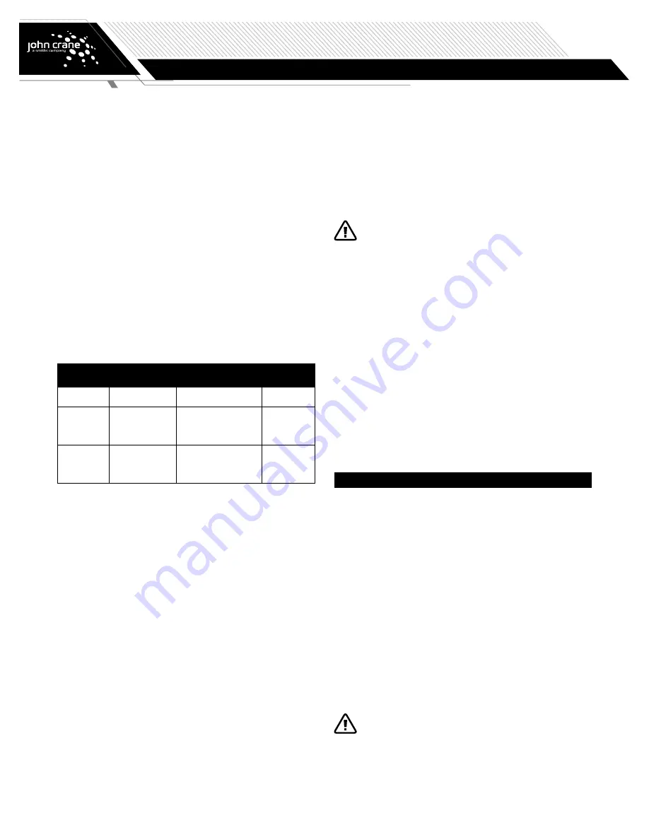
TABLE 1. Alarm Signals
Alarm Name
Instrument
Set Point
Notes
Low Pressure
/Shutdown
Required
Pressure Indicating
Transmitter (PIT) or
Pressure Switch (PS)
If barrier pressure drops
below the operating pressure
on the nameplate
REQUIRED
High Flow Alert
Flow Indicating
Transmitter (FIT) or
Flow Switch (FS)
If barrier flow rises
significantly above the value
indicated on the nameplate
RECOMMENDED
NOTE
High flow alarms are recommended as indicators of significant
deviations from normal running conditions; some fluctuation
is expected during operation. The alarm value on the
nameplate is normally several times larger than the normal
running value, and is set based on the limits of barrier gas
that can safely be injected into the machine.
e) Start the machine
f) During initial start-up it is recommended that the gas pressure/flow is
regularly monitored for correct operation. Fine tune pressure setting if
necessary.
6.2 Normal running
The equipment shall be kept clean and free from debris to allow ease
of access and reading of the instrumentation. Care should be taken to
prevent damage to the system from accidental knocks and/or exposure
to excessive sources or heat. Disconnection of any part of the system
should not be undertaken without the appropriate authorization and until
all pressure has been completely discharged and system allowed to
cool. All joints broken for maintenance should be plugged off to prevent
ingress of dirt.
During normal operation the only attention required is to monitor the
barrier gas flow. Periodic visual checking (at least every 48 hours) of the
pressure/flow within the system is recommended.
If the consumption rate of the barrier gas is low, this can result in a
phenomenon where the check valve closes fully and does not open
again until the pressure difference across the valve exceeds its cracking
pressure. This results in sudden increases in flow when the valve opens,
and then zero flow once it closes again, which will appear as pulsations
in the flow indicator/indicating transmitter. This is normal and does not
indicate a failure mode for the equipment. If the pulsations are large
enough to trigger high flow alarms, these alarm values may need to be
raised to avoid nuisance alarms.
6.3 Decommissioning
Work on the seal or system must only be carried out
when the machine is stationary, depressurized, and
secured against any unforeseen start-up. Isolation from
connections to pressurization sources must be carried out.
Before carrying out any work on the seal or system, the equipment must
be shut down and the barrier region must be fully depressurized. Once
this has been done the barrier gas supply to the Plan 74 control panel
can be isolated.
Do not isolate the barrier gas supply before the pump is made
safe.
Once the barrier gas supply is isolated carefully vent any residual
pressure from the panel and interconnecting pipe work and drain of any
liquids before carrying out any maintenance.
If the pump/panel is to be removed cover any open tubing fittings/
connections to prevent contamination.
NOTE
It is recommended that a pressure test is carried out on
the system after any repair and before operation on the
equipment.
7. Maintenance
7.1 Routine maintenance
Check the following as part of regular site walk-around checks for
trouble-free operation:
•
Check the condition of the coalescing filter element for contamination
(see Section 7.2).
•
Barrier pressure. Compare with the operating pressure on the
nameplate.
•
Barrier flow. Compare with the normal flow rate observed.
•
Condition of alarm signals (see Section 7.3).
7.2 Filter
It is recommended that the element is checked after the first month
of operation and if no contamination is detected thereafter at 6-month
intervals.
Irrespective of visual condition it is recommended that the filter element
is replaced annually.
The filter bowl is pressurized and no attempt should be
made to remove it until the barrier gas supply has been
isolated and all residual pressure in the system safely
vented. Note that the machine must also be stopped and
depressurized before removing the barrier gas pressure.


