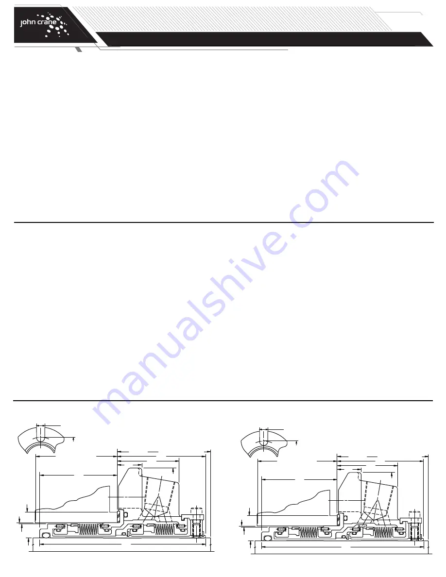
Typical Type 5625 Installation Dimensions
Typical Type 5625P Installation Dimensions
L23
L39
L91 MIN. BOX DEPTH
L92
D1
L90 MIN.
NEAREST OBSTRUCTION
D3
L12
D26
L56
D4
*MIN.
TURN
DIAM.
SLOT
WIDTH
M
N
SLOT
WIDTH
M
N
c
Assemble the Type 5625 or 5625P as follows, referring to the applicable
engineering layout drawing.
NOTE:
These instructions apply to a rotating mating ring configuration.
The seal assembly and mating ring positions could be reversed
should an application require.
NOTE:
Elastomeric O-rings can be damaged or destroyed if care is not
taken. Prior to assembly of O-ring into groove, make sure groove
is clean and free of foreign materials. Lubricate both groove and
O-ring prior to installation with light lube oil (SAE #10 or #20) or
silicone grease (such as Dow Corning compound #4.) For ethylene
propylene elastomers, do not lubricate with petroleum products.
1.
Place gland plate on table with gasket side facing up.
2.
Install lubricated O-ring into outside diameter (OD) groove of mating
ring.
3.
Stand sleeve on its base and slide mating ring over sleeve, align pins
and press in place.
4.
Install set screws in collar.
5.
Loosely attach the spacers to the collar with cap screws.
6.
Set the gland plate assembly gasket side down on table. Install collar on
gland plate assembly and engage spacers into groove, aligning spacers
with pipe taps of gland plate. Uniformly finger tighten the cap screws.
This sets the radial spacing of the cartridge.
7.
Install lubricated O-ring into outside diameter (OD) groove of seal
assembly rear adapter.
8.
Insert seal head assembly in gland plate adapter, align pins and press
in place.
9.
Clean faces of primary and mating rings with denatured alcohol and a
lint-free cloth.
10.
Stand sleeve on its base and slide seal assembly over sleeve until seal
faces touch.
11.
Install lubricated O-ring into ID groove of sleeve adapter.*
12.
Slide sleeve adapter over sleeve, aligning pins of adapter with pins of
sleeve. Push down to engage drive flats until adapter stops at step of
sleeve.
13.
Carefully slide snap ring over the end of sleeve. Using assembly tool,
push the snap ring in place inside the sleeve adapter until it snaps in
Type 5625 Dual Metal Bellows Cartridge Seal Assembly
L23
L39
L91 MIN. BOX DEPTH
L92
D1
L90 MIN.
NEAREST OBSTRUCTION
D3
L12
D26
L56
D4
*MIN.
TURN
DIAM.
*Oversize bore seals only
*Oversize bore seals only
place. Be careful not to scratch the sleeve adapter!
14.
Install lubricated O-ring into outside diameter (OD) groove of outboard
mating ring.
15.
Slide mating ring over sleeve, align pins and press in place.
16.
Install lubricated O-ring into outside diameter (OD) groove of outboard seal
assembly rear adapter.
17.
Place gland plate onto table with gasket side up.
18.
Insert seal assembly in gland plate, align pins and press in place.
Turn gland plate over and confirm that rear adapter is flush with
end of gland plate.
19.
Clean faces of primary and mating rings with denatured alcohol
and a lint-free cloth.
20.
Insert O-ring in face groove of gland plate.
21.
Making sure seal assembly does not fall out, slide gland plate over
sleeve until seal faces touch.
22.
Carefully rotate gland plate until holes in sleeve are lined up with the
collar set screws.
23.
Carefully press down on gland plate and install snap ring over the end
of sleeve.
Do not over compress gland plate or this may damage
the seal.
24.
Tighten set screws until they start to enter the sleeve ID.
25.
Uniformly tighten cap screws on spacers.
26.
Install gasket and sleeve O-ring.
27.
Pressure test according to John Crane Standard QA-5-0569.
*For 5625 or pumping ring for 5625P.
Type 5625 Dual Metal Bellows Cartridge Seal Assembly
(cont.)
TYPE 5625/5625P
DUAL METAL BELLOWS CARTRIDGE SEAL
Installation, Operation & Maintenance Instructions
PAGE
3


