John Bean EEWH553A Series Скачать руководство пользователя страница 11

 - Page 11 - 

Operation Instructions

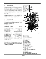
TURNTABLE & CABINET FEATURES
EEWH553A Series

TURNTABLE AND CABINET FEATURES

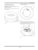
* ROUND OVERSIZED 22” TURNTABLE PLATFORM - 

Provides superior support and capacity to change up to 22” high 

performance tires. 

* INTEGRATED BEAD SEATING JETS -


Air infl ation jets are 

integrated into the turntable clamping jaws to insure full bead seating 

force directly into the


tire cavity regardless of tire diameter. 

* TWIN CYLINDER CLAMPING POWER - 

Two 3” clamping 

cylinders provide uniform clamping pressure throughout the stroke 

(regardless of rim sizes) as well as providing 25% more clamping 

power than most single clamping cylinder tire changers.  Additionally 

two smaller cylinders reduce the critical turntable to cabinet distance, 

reducing the stress on the transmission.

2-Speed Turntable with Reverse

 - Forward speed of 14 RPM 

provides faster throughput when mounting the initial bead, with a 7 

RPM standard speed providing precise control and minimizes tearing 

of tires. In the event the bead becomes jammed up on lower profi le 

performance tires, the 7 RPM reverse mode quickly relieves the 

mount/dismount head to minimize wheel damage from using a prybar.

* WHEEL CLAMPS 


UNIQUE SIX POINT CONTACT CLAMPS 


Provide better gripping capability regardless of dirt and  


 moisture. 

 REDUCED 

ANGLE 

CLAMPS 


Increases clamping contact area with rim insuring no  


slippage when clamping from outside. 


NYLON INSERT SOFT TOUCH CLAMPS 


Single sided nylon insert in the clamping jaws provides non- 


metal touch in critical customer visible areas.


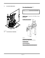
* WATER SEPARATOR AND AUTOMATIC OILER 

Lubricates all air used for machine operation, does not lubricate air 

used for tire infl ation, as do some competitive models. 

* INCOMING AIR PRESSURE GAUGE 

Ergonomically located air gauge allows easy monitoring of incoming 

air pressure 

* INTEGRATED PRESSURE LIMITER 

Integrated safety pressure limiter stops air fl ow once pressure has 

reached 55 PSI preventing accidental tire over-infl ation. 

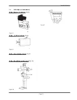
MOUNT/DEMOUNT ARM ASSEMBLY 

* PNEUMATIC TOWER TILT -


Mount/Demount tower automati-

cally tilts back  with the single push of a foot operated pedal. 

* ADJUSTABLE SLIDEWAY -


Unique adjustable mount/demount 

shaft slideway allows for easy operator adjustment to compensate for 

any cumulative wear in the slideway causing mount/demount head 

movement. 

* NON-SCRATCH NYLON INSERT - 

Integrated into the mount/

demount head is a scratch resistant nylon insert protecting against 

accidental rim contact.

RACING/HIGH PERFORMANCE MODIFICATIONS

* HIGH TORQUE 1HP MOTOR - 

Industrial strength high  torque  turntable drive motor ensures 

smooth, quiet operation.

* PNEUMATIC OPERATED DOUBLE LOCK

 - Unique design 

provides the ultimate in mount/demount head rigidity by pneumati-

cally locking the arm at two separate points, with the push of a thumb 

activated button. 

* INCREASED TOWER STRENGTH

 - 

Square Mount/Demount 

tower has increased steel thickness (.24”), increased horizontal arm 

(2”x2 3/4”) to minimize any fl ex while mounting high performance 

tires.


SAFETY RESTRAINT ARM

* TIRE/RIM ASSEMBLY RESTRAINT - 

Safety Restraint Arm 

positively restrains tire and rim assembly to the tire machine during 

the infl ation process reducing potential for injury caused by the 

unlikely event of  catastrophic tire or rim failure. 

* SIMPLE SWING ARM DESIGN - 

SRA arm easily swings to 

the left when not in use allowing the technician to quickly and safely 

perform the infl ation process without disrupting the tire changing 

procedure. 

* GRAVITY LOCK - 

SRA  lock mechanism operates without any 

mechanical cam system eliminating the possibility of system deterio-

ration or mis-adjustment  from mechanical wear. 

* POSITIONING SAFETY INTERLOCK SWITCH - 

Integrated 

switch insures that SRA arm is centered on the tire/rim assembly 

before the infl ation  process can begin. 

* ANTI-ROTATION LOCK

 -

 Prevents SRA from rotating during 

infl ation process.

CONSTRUCTION DESIGNED FOR DURABILITY 

* RUST PROOF VALVES AND CYLINDERS -


Critical bead 

breaking cylinder is lined with rustproof polyfi ber liner for years of rust 

free operation.

* LIFETIME LUBRICATED POLYMER VALVES -


Critical foot-

valves


fabricated from glass/fi ber self lubricating material providing 

years of maintenance free operation. 

Содержание EEWH553A Series

Страница 1: ...High Performance Tire Changer Operation Instructions Form ZEEWH553AE ...

Страница 2: ... BLANK PAGE ...

Страница 3: ...in this document is property of Snap on Equipment division of Snap on Incorporated It or any of the informa tion contained within shall not be used copied or reproduced without express written consent of Snap on Equipment or its holding com pany ...

Страница 4: ... BLANK PAGE ...

Страница 5: ...he automotive technician s responsibility to be knowledgeable of the wheels and tires being changed It is essential to use proper service methods and change tires in an appropriate and acceptable manner that does not endanger your safety the safety of others in the work area or the equipment or vehicle being serviced It is assumed that prior to using the EEWH553A Series Tire Changers the operator ...

Страница 6: ...ater than that of the equipment should be used Cords rated for less current than the equipment can overheat Unplug equipment from electrical outlet when not in use Never use the cord to pull the plug from the outlet Grasp plug and pull to disconnect Do not expose the equipment to rain Do not use on wet surfaces Plug unit into correct power supply Do not remove or bypass grounding pin Contact with ...

Страница 7: ... use tools other than those supplied with tire changer Do not bypass any safety features Use proper tire lubricate to prevent tire binding Contact with moving parts could cause injury Risk of eye injury Flying debris dirt and fluids may be discharged during bead seating and inflation process Remove any debris from tire tread wheel surfaces Remove excess tire lubricant before inflating Wear approve...

Страница 8: ...safety inflation cage designed for this purpose Lock turntable Clamp on inside of rim before attempting to inflate tire Use approved tire bead lubricant before removing or installing tire on rim ALWAYS position the Safety Restraint Arm over the wheel to hold it to the turntable while inflating if so equipped If a tire explodes on this tire changer STOP using it until the Safety Restraint Arm has b...

Страница 9: ...Installation Page 14 2 1 Electric Installation Page 14 2 2 Bead Breaker Installation Page 15 2 3 Air Installation Page 15 3 0 Controls Page 16 4 0 Mounting and Demounting precautions Page 17 4 1 Demounting Tubeless Tires Page 17 4 2 Mounting Tubeless Tires Page 20 4 3 Inflating Tubeless Tires Page 21 5 0 Demounting Tube Type Tires Page 23 5 1 Mounting Tube Type Tires Page 23 5 2 Inflating Tube Typ...

Страница 10: ...Maximum Rim Width 15 381mm Maximum Tire Diameter 40 1016mm Turn Table Operation Dual Speed with Reverse Turn Table Torque lb ft 885 Turn Table Speed RPM 7 and 14 CW 7 CCW Bead Breaker Force 3 300 lbs 150 PSI Bead Breaker Opening ADJ 2 5 12 5 or 3 15 Air Pressure Required 110 to 170 psi 8 12bar Electrical Requirements 230V 60Hz 1 ph 12A Tire profile may effect machines ability to completely break b...

Страница 11: ...SSEMBLY PNEUMATIC TOWER TILT Mount Demount tower automati cally tilts back with the single push of a foot operated pedal ADJUSTABLE SLIDEWAY Unique adjustable mount demount shaft slideway allows for easy operator adjustment to compensate for any cumulative wear in the slideway causing mount demount head movement NON SCRATCH NYLON INSERT Integrated into the mount demount head is a scratch resistant...

Страница 12: ...ool Fig 3 294 Figure 3 Inflation Gauge is mounted on the Inflation Column Not shown Air Filter and Air Lubricator Fig 4 539 Figure 4 Incoming Air Pressure Gauge Located on the air filter and the air lubricator Lubrication Bottle Lubrication Applicator Replacement Mount Demount Head Inserts 4 ...

Страница 13: ...ion Instructions 1 5 OPTIONAL ACCESSORIES 87435 Motorcycle Adapter Fig 5 320 Figure 5 87436 8 Wheel Adapter Fig 6 316 Figure 6 66735 Bead Holding Clamp Fig 7 315 Figure 7 Figure 5a 87434 Mount Demount Assisant Fig 5a ...

Страница 14: ...ooden skid Remove tire changer from its mounts carefully taking care to avoid any back strain Place Changer where proper operation will be unobstructed to all sides Install the machine in a covered and dry place 2 0 1 Models with SRA attached Optional Once placed in the desired location the tire changer must be bolted to the floor using only the rear two mounting holes Mounting anchors are provide...

Страница 15: ...formance It is suggested that the air supply be equipped with a water separator dryer type modification for maximum performance After ensuring all the above proceed as follows A Connect the machine to the air sup ply with a rubber hose rated for the pressure with an internal diameter of no less than 1 2 12 5mm WARNING BEFORE CONNECTING THE MACHINE TO THEAIR SUPPLY BE SURE ALL PERSONNEL ARE CLEAR O...

Страница 16: ...the bead breaker arm Press down and hold the second pedal 2 from the left by doing this you operate the bead breaker blade and the arm will move towards the machine Release the pedal the bead breaker blade will retract D Press down and hold the second pedal from the right the turntable turns clockwise 1 3 4 down approximately the turntable rotates at the minimum speed 7 RPM The torque is maximum i...

Страница 17: ...ntArm 7 swings to center of the turntable I Lift upward on the restraint positioning knob 8 to posi tion over tire wheel assembly for inflation at the same time push down on theAnti rotation LockArm to release lock 9 You may now swing the safety restraint arm to position on the center of the wheel Lower the restraint until the rubber pad on the restraint disc is resting on the rim center The SRA i...

Страница 18: ...ne Make certain that the bead breaker blade is not over the top of any portion of the rim Now activate the bead breaker pedal As soon as the bead dislodges from the rim release the breaker foot pedal It may be necessary to rotate the tire 90 degrees and repeat the above procedure to dislodge all beads Pay extra attention during this operation as it is easy to mistakenly keep your foot on the bead ...

Страница 19: ...DI CALLY REPLACED MAINTENANCE NOTE IF THE MOUNT DEMOUNT HEAD NYLON INSERTS ARE WEARING OUT PREMATURELY THE CAUSE IS THE OPERATORS FAILURE TO CORRECTLY SET THE SWING ARM ADJUSTMENT KNOB CAUSING THE INSERT TO INCORRECTLY CONTACT THE RIM NOTE ONCE THE MOUNT DEMOUNT HEAD IS POSITIONED PROPERLY IDENTICAL WHEELS MAY BE CHANGED WITHOUT HAVING TO RESET THE HEAD F Insert the mount demount tool under the be...

Страница 20: ...he bead into the drop center of the rim Fig 16 334 Fig 17 H Repeat the process for removing the lower bead This time lift the bead opposite to the mount demount head to keep it in the drop center Fig 17 Move the swing arm aside and remove the tire 335 DANGER Keep hands and fingers clear of mount demount head during operation ...

Страница 21: ...he turntable and rotate it so that the valve is at the 2 o clock position Place the tire to be mounted on the rim Move the mount demount head to ward it s forward working position Fig 20 Engage the lower bead OVER the mount demount head and UNDER the mounting finger of the mount demount head Fig 20 Turn the wheel clockwise right pedal down while simulta neously pushing the tire down into the drop ...

Страница 22: ...on lock arm Swing safety arm assembly so the circular retainer is centered over the rim Note that air pressure to the inflation hose will not flow until the arm is centered over the rim B If possible lock the wheel from inside Outside locking reduces efficiency C Connect the inflation hose to the valve stem D Lift the tire with both hands so that the upper bead is sealed to the rim edge Fig 21 NEV...

Страница 23: ...at the tube is the correct size for the tire to be mounted Fig 23 341 Fig 23 C Inflate the tube slightly if held with the index finger it should bend a little Fig 24 342 Fig 24 D Mount the first bead as described in section 4 2 B Put the tube inside the tire and connect the inflation air line to the tube valve to hold the tube in place Fig 25 Mount the top bead following the directions above 343 F...

Страница 24: ...TED THE OPERATOR MUST STAND CLEAR FROM THE WHEEL WHEN INFLATING AND PRESSURE MUST BE MONITORED FREQUENTLY TOAVOID OVER INFLATION BEFORE INFLATING A TIRE CHECK THE CONDITION OF THE TIRE AND THE RIM To inflate the tire unlock the rim and start inflating while pressing the valve towards the inside this is necessary to avoid air pockets forming between tube and the tire Fig 26 Ensure that the tire is ...

Страница 25: ... knob B clockwise and upward Water will au tomatically be discharged see B at Fig 29 I Check the automatic air lubricator oil level weekly When adding oil to the lubricator disconnect the air supply first remove the fill screw A and add oil as needed Make sure seals are in place when replacing the cap 553 Fig 29 NOTICE USE ONLY OILS FOR AIR DEVICES DO NOT USE BRA KE FLUID OR OTHER NON SUGGESTED LU...

Страница 26: ...inal spare parts and accessories The installation should be performed by qualified per sonnel and within respect of the instructions provided for within this manual Check for possible dangerous conditions during the operation of the machine In such a case Cease op eration immediately If a malfunctioning condition is detected stop using the machine and call the authorized JBC Representative for ass...

Страница 27: ...f 110 psi the force of the device may be insufficient for certain types of tires After checking all the above proceed as follows DISCONNECT ELECTRIC AND AIR SUPPLY FROM THE CHANGER BEFORE INSTALLATION OF THIS DEVICE 3 1 INSTALLATION INSTRUCTIONS A Place the drilled template spacer plate A as shown in Figure 1 The square angle must be in contact with the side wall of the Cabinet and with the reinfo...

Страница 28: ...e same hole in the rear of the cabinet as hose 1 E Attach the hose 3 to the Tee fitting 2 on hose 1 F Close the side panel of the tire changer and secure with the lock screw 4 0 NOMENCLATURE Before using the 87434 Bead Assist Attachment it is suggested that you become familiar with the nomen clature of components Figure 4 1 Raise Descent control 2 Roller 3 Handle 4 Roller release lever 5 Horizonta...

Страница 29: ...ead as described in the tire changer operator s manual B Loser the column position the lower bead push de vice next to the lower rim edge Hold the handle firmly press the raise button and at the same time rotate the turntable Figure 6 This operation allows to loosen the bead if this is stuck and helps lifting the tire NOTE A CERTAIN EFFORT ON THE HANDLE OF THE LOWER BEAD PUSH DEVICE IN A RADIAL DI...

Страница 30: ... BLANK PAGE ...

Страница 31: ... BLANK PAGE ...

Страница 32: ...s performance or use of this material This document contains proprietary information which is protected by copyright and patents All rights are reserved No part of this document may be photocopied reproduced or translated without prior written consent of Snap on Equipment or its holding company ZEEWH553AE REV A 09 23 13 wdc copyright 2013 Snap on Equipment Printed in the USA Snap on Equipment 309 ...

Отзывы: