background image

1U SCSI JBOD

4-bay Rackmount Enclosure

Installation Guide

October 3, 2002     •     Revision A

Patent Pending

StorBlade

TM

Содержание 1U SCSI JBOD

Страница 1: ...1U SCSI JBOD 4 bay Rackmount Enclosure Installation Guide October 3 2002 Revision A Patent Pending StorBladeTM ...

Страница 2: ...e original product packaging has been tested and is safe under normal shipping circumstances Reshipping the product without using the original product packaging will void the warranty Do not ship the unit with canisters or power supplies installed as this will void the warranty and could cause damage to the unit and drives The canisters should be packaged separately within the product packaging as...

Страница 3: ...Compliance 2 2 Packaging Specifications 2 2 Disclaimer 2 2 Thermal Specifications 2 3 Rotation Vibration Specifications 2 3 Fault Indication Features 2 3 Fault Indicators 2 3 Audible Alert 2 3 3 Device Installation SCA Connection and Hot Swapping 3 1 Canister Removal Insertion 3 1 Drive Installation 3 1 4 SCSI Setup Basic Personality Card Setup 4 1 Setting ID 4 2 Available ID s 4 2 ID Conflict 4 3...

Страница 4: ...lation 6 2 7 Product Support US Corporate Headquarters 7 1 Manual Changes 7 1 Appendix A Drive and Controller Manufacturers Drive Manufacturers A 1 RAID Controller Manufacturers A 1 Host Bus Adapter Manufacturers A 2 S St to or rB Bl la ad de eTM SCSI JBOD Installation Guide Rev A iv StorBladeTM ...

Страница 5: ...rs 1 1 1 or 2 2 2 2 2 2 Number of Power Supplies 1 1 1 or 2 2 2 2 2 1 or 2 Number of I O Channels SCSI Only 1 1 2 2 2 2 2 SCSI SE LVD Supported 2 2 2 2 2 2 2 Fibre Channel Supported 2 2 2 2 2 2 Hot Swap Canisters 2 2 2 2 2 2 2 2 Removable Power Supplies 2 2 2 2 2 2 2 Fibre only Removable Blowers 2 2 2 2 2 2 2 Fibre Only N 1 Power Supplies 2 2 2 2 2 Fibre only N 1 Blowers 2 2 2 2 2 2 MIA Support FC...

Страница 6: ...A Blower Quantity 2 Size 70mm 2 75 each Air Flow 11 3CFM 0 32m3 min each Noise 38dB A SCSI Features Daisy Chaining StorBladeTM SCSI enclosures include a SCSI I O OUT port to allow additional devices and enclosures to be daisy chained easily onto the bus The limit of devices and enclosures that can be added is only regulated by the maximum cable length and maximum number of devices as specified by ...

Страница 7: ... Sentinel 2500 50 w IFT9282F Fibre Host LVD Drives I3 Infortrend EonRAID 2500 50 w IFT9288B6B Fibre Host LVD Drives I4 Infortrend EonRAID 5251F 2G Fibre Host 2G Fibre Drives I5 Infortrend SentinelRAID 150 LVD Host LVD Drives IS Infortrend EonRAID 7250 12U3D SCSI Host ATA Drives IF Infortrend EonRAID 7250 12F2D Fibre Host ATA Drives M3 Mylex DAC FFx 1G Fibre Host 1G Fibre Drives M5 Mylex DAC FFx2 2...

Страница 8: ... the warranty Packaging complies with ISTA International Safe Transit Association standards and has been ISTA certified Each canister is pre packaged in an anti static bag Do not throw the packaging away if the product is intended for re shipping When transporting or shipping a JMR approved shipping container must be used Disclaimer The original product packaging has been tested and is safe under ...

Страница 9: ...hock requirements for popular 7 200 10 000 and 15 000 RPM disk drives Fault Indication Features This section reviews the indicators that will notify the user of a power supply or blower that is in a fault state More information is available in Chapter 5 power supply and blowers Fault Indicators All slots will blink Red in color on a blower fault On a power supply fault the front power supply LED w...

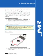
Страница 10: ...onal cabling or connections Canister Removal Insertion 1 Pull the handle out to unlock the canister from the StorBladeTM unit Notice that the locking tab slides down as the handle is pulled out 2 Pull the canister straight out to remove Ensure that any installed devices are spun down before full removal to prevent damage to the drive Follow the steps in reverse to reinstall Drive Installation 1 Af...

Страница 11: ...ng the screws included with the unit use all 4 screws to mount the drive 3 Replace the canister into the unit 4 Repeat steps 1 through 3 until all devices are installed 5 Configure ID and other options as required 6 Establish host connection S St to or rB Bl la ad de eTM SCSI JBOD Installation Guide Rev A 3 2 StorBladeTM ...

Страница 12: ...ie sich daß die Netzspannung 220V 110V korrekt eingestellt ist bevor Sie das Gerät mit dem Stromnetz verbinden Zur Sicherheit sollte das Netz über einen Überspannungsschutz zur Vermeidung von Schäden im Falle einer Überlast verfügen WARNING When connecting the unit to an AC outlet or power strip ensure that the outlet has the proper connection for grounding The AC power cables included with the un...

Страница 13: ... ID of each slot Header W1 is for slot 3 Header W2 is for slot 2 Header W3 is for slot 1 Header W4 is for slot 0 Available ID s Each bus is allowed to have ID s that range from 0 15 No two devices on the same bus may share the same ID Each host controller always uses one ID The Figure above shows all 0 15 possible ID settings S St to or rB Bl la ad de eTM SCSI JBOD Installation Guide Rev A 4 2 Sto...

Страница 14: ...re is a system fault A system fault is either a power supply or blower failure The power supply and blowers are not field replaceable units A fault with either the power supply or blowers will require replacement of the entire unit Refer to Chapter 5 External I O Connection The external I O connections are located on the back of the unit The figure below shows the external I O connections availabl...

Страница 15: ...bus SCSI I O Out ports require a cable with a 68 pin High Density male connector to mate When daisy chaining the SCSI I O Out port of the enclosure is connected to the SCSI I O In port of the enclosure or device being added Ensure that when new devices are added to the SCSI bus that the ID does not have a conflict Once the units are connected together termination must be moved to the last device o...

Страница 16: ...MR part numbers and descriptions Please contact a JMR representative for current availability and pricing JMR SCSI CABLES JMR Part Ends Connector Type Length FT CBL 00532 Molded SCSI 3 to SCSI 3 3 CBL 00534 Molded SCSI 3 to SCSI 3 6 S St to or rB Bl la ad de eTM SCSI JBOD Installation Guide Rev A 4 5 StorBladeTM ...

Страница 17: ...pply malfunction contact Technical Support at JMR Electronics See Chapter 7 for contact information Blower Removal Insertion In the 1U04 SCSI JBOD enclosure there are two blowers that are not field replaceable units If a blower malfunction occurs please contact JMR Electronics See Chapter 7 for contact information S St to or rB Bl la ad de eTM SCSI JBOD Installation Guide Rev A 5 1 5 Power Supply ...

Страница 18: ...ont and back of the unit are not blocked when installing the unit into a cabinet or closed area Blocking the front or back of the unit can cause reduced air flow that will compromise the safe operating environment within the unit WARNUNG Vergewissern Sie sich daß das Gerät an Vorder und Rückseite nicht abgedeckt ist wenn das Gerät in einem Gehäuseschrank oder einer geschlossenen Umgebung verbaut w...

Страница 19: ... 01580 8 32 Screw HDS 00350 8 32 Nut HDN 00040 8 32 Washer HDW 00080 Rail Installation 1 Affix the extension brackets to the main rail using the 8 32 screw washer nut assemblies Adjust to the correct length for the cabinet depth being used S St to or rB Bl la ad de eTM SCSI JBOD Installation Guide Rev A 6 2 StorBladeTM Main Rail Front Expansion Rail Rear Front of Rackmount Unit Two 8 32 Screws Was...

Страница 20: ...The fronts of the rails have three holes Two of the holes top and bottom are used to secure the rail to the cabinet The middle hole is used to secure the enclosure to the rail and cabinet Secure the front of each rail to the cabinet vertical rails using two 10 32 screws for each rail 4 Slide the unit into the cabinet and secure it to the cabinet by tightening the two embedded thumb screws S St to ...

Страница 21: ...b page at www jmr com or you can contact our Technical Support division directly at the address below US Corporate Headquarters JMR Electronics Inc ATTN Technical Support Division 20400 Plummer St Chatsworth CA 91311 Customer Support 818 739 1140 E mail techsupport jmr com Office Hours Monday Friday 8 00 A M to 5 00 P M Pacific Standard Time Internet http www jmr com Manual Changes Revision A Init...

Страница 22: ...ess www seagate com RAID Controller Manufacturers Adaptec Inc Internet Address www adaptec com Chaparral Network Storage Internet Address www chaparralnet com Digi Data Corporation Internet Address www digidata com Infortrend Corporation Internet Address www infortrend com Intel ICP VORTEX Intelligent Computer Peripherals Internet Address www icp vortex com Mylex Corporation Internet Address www m...

Страница 23: ...m Antares Microsystems Internet Address www antares com Emulex Corporation Internet Address www emulex com JNI Corporation Internet Address www jni com QLogic Corp Internet Address www qlogic com S St to or rB Bl la ad de eTM SCSI JBOD Installation Guide Rev A A 2 StorBladeTM ...

Отзывы: