SECTION 3 - CHASSIS & TURNTABLE
3-60
3121200
Wear Tolerance
1.
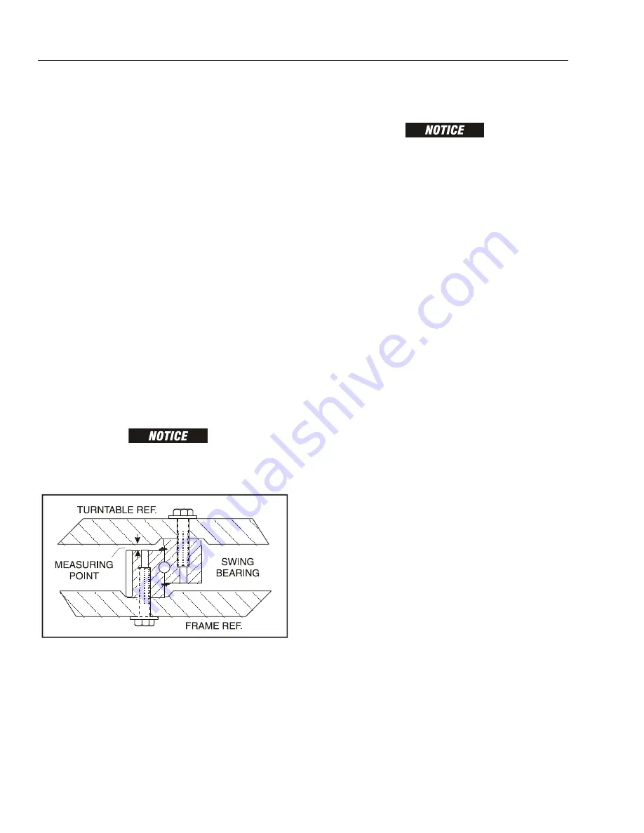
From the underside of the machine, at rear center, with
the main boom fully elevated and fully retracted, using a
magnetic base dial indicator, measure and record the
distance between the swing bearing and turntable. See
Figure 3-28., Swing Bearing Tolerance Measuring Point
2.
At the same point, with the main boom at horizontal
and fully extended, using a magnetic base dial indicator,
measure and record the distance between the swing
bearing and turntable. See Figure 3-28., Swing Bearing
Tolerance Measuring Point.
3.
If a difference greater than 0.057 in. (1.40 mm) is deter-
mined, the swing bearing should be replaced.
4.
If a difference less than 0.057 in. (1.40 mm) is deter-
mined, and any of the following conditions exist, the
bearing should be removed, disassembled, and
inspected for the following:
a.
Metal particles in the grease
b.
Increased drive power required
c.
Noise
d.
Rough rotation
5.
If bearing inspection shows no defects, reassemble and
return to service.
THE SWING BEARING IS ONE OF THE MOST CRITICAL POINTS ON AN AERIAL
LIFT. IT IS HERE THAT THE STRESSES OF LIFTING ARE CONCENTRATED, AT THE
CENTER OF ROTATION. BECAUSE OF THIS, PROPER MAINTENANCE OF THE
SWING BEARING BOLTS IS A MUST FOR SAFE OPERATION.
Swing Bearing Removal
HYDRAULIC LINES AND PORTS SHOULD BE CAPPED IMMEDIATELY AFTER DIS-
CONNECTING LINES TO AVOID THE ENTRY OF CONTAMINANTS INTO THE SYS-
TEM.
1.
Remove the boom assembly. refer to Section 4.3, Boom
and Cylinder Assembly.
2.
Tag and disconnect the hydraulic lines from the fittings
on the turntable. Use a suitable container to retain any
residual hydraulic fluid. Immediately cap lines and ports.
3.
Attach suitable overhead lifting equipment to the base
of the turntable.
4.
Use a suitable tool to scribe a line on the inner race of
the swing bearing and on the underside of the turnta-
ble. This will aid in aligning the bearing upon installa-
tion. Remove the bolts and washers which attach the
turntable to the bearing inner race. Discard the bolts.
5.
Use the lifting equipment to carefully lift the complete
turntable assembly from the bearing. Ensure that no
damage occurs to the turntable, bearing or frame-
mounted components.
6.
Carefully place the turntable on a suitably supported
trestle.
7.
Use a suitable tool to scribe a line on the outer race of
the swing bearing and the frame. This line will aid in
aligning the bearing upon installation. Remove the bolts
and washers which attach the outer race of the bearing
to the frame. Discard the bolts. Use suitable lifting
equipment to remove the bearing from the frame, then
move the bearing to a clean, suitably supported work
area.
Figure 3-28. Swing Bearing Tolerance Measuring Point
Содержание T500J
Страница 1: ...Service and Maintenance Manual Model T500J PN 3121200 July 25 2018 Rev I AS NZS...
Страница 2: ......
Страница 16: ...xii 3121200 LIST OF TABLES TABLE NO TITLE PAGE NO This page left blank intentionally...
Страница 36: ...SECTION 2 GENERAL 2 8 3121200 NOTES...
Страница 115: ...SECTION 3 CHASSIS TURNTABLE 3121200 3 79 MAE29600 DRIVE MOTOR SPINDLE 1 Figure 3 37 Wheel Drive Removal and Installation...
Страница 136: ...SECTION 3 CHASSIS TURNTABLE 3 100 3121200 Figure 3 41 Battery Cable Routing Prior to SN 0030001804...
Страница 143: ...SECTION 3 CHASSIS TURNTABLE 3121200 3 107 Figure 3 45 Battery Charger Schematic...
Страница 213: ...SECTION 5 BASIC HYDRAULIC INFORMATION SCHEMATICS 3121200 5 39 This page left blank intentionally...
Страница 234: ...SECTION 5 BASIC HYDRAULIC INFORMATION SCHEMATICS 5 60 3121200 NOTES...
Страница 246: ...SECTION 6 JLG CONTROL SYSTEM 6 12 3121200 Figure 6 5 System Test Flow Chart Platform Tests...
Страница 248: ...SECTION 6 JLG CONTROL SYSTEM 6 14 3121200 Figure 6 6 System Test Flow Chart Ground Station Tests...
Страница 283: ...SECTION 7 BASIC ELECTRICAL INFORMATION SCHEMATICS 3121200 7 11 Figure 7 17 Connector Installation...
Страница 297: ...SECTION 7 BASIC ELECTRICAL INFORMATION SCHEMATICS 3121200 7 25 This page left blank intentionally...
Страница 304: ...SECTION 7 BASIC ELECTRICAL INFORMATION SCHEMATICS 7 32 3121200 NOTES...
Страница 305: ......


