JLG Power Towers Nano Скачать руководство пользователя страница 9

Please note that whilst the Nano is extremely simple to maintain, 
all work must be carried out by a competent person.

When removing checkerplate cover for maintenance purposes, 
first switch off by depressing the emergency stop/battery isolator 
button located at the base of the machine. Use appropriate 
safety/personal protective equipment where necessary.
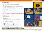
DAILY MAINTENANCE

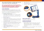
Tilt cage by releasing gate latch on cage mount (see pic).  Pull cage 
frame from gate end and cage will lift and tilt assisted by gas strut.  
Ensure gas strut is fully extended and that the safety chock is in place.  
You can now access the powerpack housing. Unscrew the black 
retaining knobs and lift out the checkerplate cover.

1.


Check Battery Electrolyte Level:


Remove battery cover and battery caps. Ensure the electrolyte    


covers the plates by no more than 1mm – 2mm. Replenish with  


distilled water to this level, only if the electrolyte level is below   


the top of the plates. 

2.     Check Hydraulic Oil Level:
  

Ensure the tank is not overfilled. The level must only be checked


  when the machine is in the transport position. The correct level


  in this condition is approximately 3/4 from the base of the tank,


  as indicated by the line.

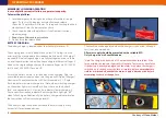
3.     Ensure there is no obvious mechanical damage 

to the handrails,


  entrance gate, post or structure of chassis. Also check the castors


  and wheels are undamaged, rotate freely and are secured


  to machine.

4.     Check hydraulic connections 

around the pump and base of


  cylinder are tight and undamaged.

5.     Check the spirit level 

to ensure it is clearly legible and

   undamaged.

6.     Check all functions 

operate correctly including movement alarm


  and emergency stops.

7.     Ensure mast surfaces are clean and not greased.

WEEKLY MAINTENANCE

Check battery terminal connections are tight.

MONTHLY MAINTENANCE

Check Battery Specific Gravity:


  On a monthly basis check the specific gravity in each of the


  battery cells. When a battery is correctly fully charged the


  specific gravity should be 1.27 - 1.3. The specific gravity


  reading should be equal across the cells, if not repeat the full


  charge cycle.

Check rollers and mast surfaces for damage. Ensure brushes are fitted
correctly and brush against mast surface.

MAINTENANCE PROCEDURES
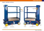
9

Cage mount 

gate latch

Courtesy of Crane.Market 

Содержание Power Towers Nano

Страница 1: ...Operating and Maintenance Manual www powertowers com Courtesy of Crane Market...

Страница 2: ...ork from The Nano eliminates many of the risks associated with portable scaffold towers The Nano is suitable for any application provided it is used within its specified operating parameters If used f...

Страница 3: ...Maximum total weight Inc payload 485 kg Maximum castor point load 180 kgs 1 77 kN Max wheel force 1 75 kN Closed Dimensions Length 1 195 m Width 0 750 m Height 1 560 m Weight 285 kg Power Source Stand...

Страница 4: ...he Nano on sloping or uneven ground 3 Never use the Nano as a goods lift or crane 4 Never exceed horizontal forces never use in wind maximum horizontal force 200N 5 Never use in the vicinity of live c...

Страница 5: ...Y COMPONENTS PRIMARY COMPONENT LOCATIONS 5 Control Box Entrance Gate Latch Spirit Level Swivel Castor Auto Lok Braked Wheel Emergency Stop Battery Isolator Emergency Lowering Valve Courtesy of Crane M...

Страница 6: ...Emergency operation How to lower the Nano without power or in the event of operator incapacity There is no specific legal requirement to wear a safety harness However there is an employers requiremen...

Страница 7: ...achine under application Refer to working envelope diagram if necessary 1 Apply both castor brakes 2 Check spirit level to ensure machine is level 3 Ensure the emergency lowering valve is closed push...

Страница 8: ...ly and ensure the green LED top of charger illuminates The adjacent amber LED has three modes C 1 Rapid flash indicates maximum charge rate Note when switching charger on the amber light must rapid fl...

Страница 9: ...ly be checked when the machine is in the transport position The correct level in this condition is approximately 3 4 from the base of the tank as indicated by the line 3 Ensure there is no obvious mec...

Страница 10: ...the application any failure could result in a serious accident Secondly if the bearings become tight then it will make the machine difficult to manoeuvre A measure of horizontal push force can simply...

Страница 11: ...ng with a spacer washer that enables a higher bolting torque to be applied This will improve the reliability of the fix but will not increase the strength of the castor assembly The new fixing nut and...

Страница 12: ...ghly rated for the application so if visible distortion is evident a significant impact will have occurred and under these conditions the castor and fixing must be replaced Typical signs of impact whi...

Страница 13: ...the lower rest buffers and the outer section continues to close over the middle section It is essential the mast closes in this sequence To ensure the mast sections move in the correct sequence and d...

Страница 14: ...ondition and security Axle and wheels for condition and security Condition and operation of spirit level Condition of component and battery covers Condition of all labelling Carry out a full operation...

Страница 15: ...his is not practical then the charger should be switched on once a week for half an hour This is especially important in cold conditions The hydraulic oil must be replaced recommended after 3 months o...

Страница 16: ...tery Charger PT E 001 E 12V 105A Traction Battery PT E 002 F 110V Plug PT E 010 HYDRAULIC PARTS Part No G 12V DC Powerpack Complete PTN H 251 H Emergency Lowering Solenoid c w Valve PTN H 255 Emergenc...

Страница 17: ...106 E Guardrails c w Gate PTN M 350 F Rubber Buffer PT M 126 G Cover Securing Knob PT M 107 H Tool Tray PTN M 303 I Buffer Wheel PTN M 302 J Decal Set complete PTN M 322 K Keys pair PTN M 341 L Gas St...

Страница 18: ...OP ISOLATOR E STOP RED UNUSED BROWN VE GREEN YELLOW DOWN BLUE UP UP N O 5A MOVEMENT ALARM VE VE SUZIE CABLE 110V 230V AC SUPPLY 15A LOWERING VALVE SOLENOID 12V DC MOTOR CONTACTOR 1 POWERPACK 2 PIN CON...

Страница 19: ...CIRCUIT DIAGRAM HYDRAULIC 19 Relief Valve preset to 65 Bar 12V DC Powerpack Single Action 2 stage lift cylinder Manual Bypass Solenoid Lock Valve NA HP 003 Steel Pipe Orifice Courtesy of Crane Market...

Страница 20: ...t a warranty claim on any Nano or component Materials and or labour costs to renew repair or replace components due to fair wear and tear Faults arising from the use of non standard or additional part...

Страница 21: ...Courtesy of Crane Market...

Страница 22: ...Courtesy of Crane Market...

Страница 23: ...Courtesy of Crane Market...

Страница 24: ...N OP UK 11 15 4 www powertowers com 100 British designed and manufactured Powered by TCPDF www tcpdf org Courtesy of Crane Market...

Отзывы: