SECTION 3 - CHASSIS, PLATFORM, & SCISSOR ARMS
31215923
3-65
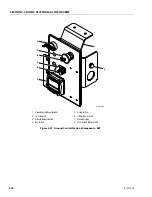
Platform Control Station
DISASSEMBLY
1. Disconnect the cable from the harness connector on
the underside of the platform control station.
2. Remove the display shield by removing hardwares
securing display shield (6) to upper extrusion hous-
ing (1).
3. Disconnect all hydraulic and electrical connection
going to display.
4. If required, remove the hardware securing control
box latch pin (5) and remove it.
5. Supporting the upper extrusion housing assembly,
remove the three stud (2) and hardware securing
upper extrusion housing (1) to control box side panel
(7). Carefully remove lower extrusion housing (2).
6. Supporting the lower extrusion housing assembly,
remove the three stud (2) and hardware securing
lower extrusion housing (3) to control box side panel
(7). Carefully remove lower extrusion housing (2).
7. Remove the four screws and nuts to remove the joy-
stick controller (4).
8. The harness can be removed from the box by remov-
ing the harness connector terminal nut (4), and dis-
connecting all the wiring inside the control box.
ASSEMBLY
1. Follow Disassembly Procedures in reverse.
2. Ensure electrical wires are properly and securely
attached to switches, buttons and bulbs.
NOTE:
Ensure wires are not pinched when installing the
loaded control box plate back onto the mounting
bracket.
NOTE:
Apply medium Strength Threadlocking Compound
to hardware.
3. Reattach wiring cable to harness connector (4) on
underside of platform control station.
4. Mount control station to platform rail.
5. Operate functions with platform control console to
ensure proper operation.
1.
Upper Extrusion Housing
2.
Stud
3.
Lower Extrusion Housing
4.
Joystick Controller
5.
Control Box Latch Pin
6.
Display Shield
7.
Control Box Side Panel
8.
Display Panel
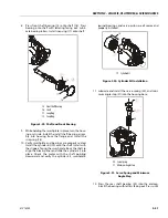
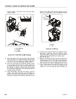
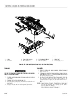
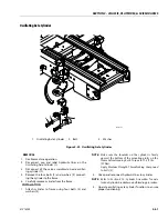
Figure 3-45. Platform Control Station
MAF42140
1
6
4
7
5
2
3
8
Содержание ERT2669
Страница 2: ......
Страница 4: ...INTRODUCTION A 2 31215923 REVISON LOG Original Issue A January 08 2021...
Страница 12: ...viii 31215923 TABLE OF CONTENTS...
Страница 40: ...SECTION 1 SPECIFICATIONS 1 22 31215923...
Страница 58: ...SECTION 2 GENERAL 2 18 31215923...
Страница 187: ...SECTION 4 BASIC HYDRAULIC INFORMATION SCHEMATICS 31215923 4 11...
Страница 206: ...SECTION 4 BASIC HYDRAULIC INFORMATION SCHEMATICS 4 30 31215923...
Страница 221: ...SECTION 4 BASIC HYDRAULIC INFORMATION SCHEMATICS 31215923 4 45 Figure 4 33 Lift Cylinder MAF46290...
Страница 223: ...SECTION 4 BASIC HYDRAULIC INFORMATION SCHEMATICS 31215923 4 47 Figure 4 35 Leveling Jack Cylinder MAF46280...
Страница 225: ...SECTION 4 BASIC HYDRAULIC INFORMATION SCHEMATICS 31215923 4 49...
Страница 242: ...SECTION 4 BASIC HYDRAULIC INFORMATION SCHEMATICS 4 66 31215923...
Страница 307: ...SECTION 5 JLG CONTROL SYSTEM 31215923 5 65...
Страница 334: ...SECTION 6 LSS SETUP CALIBRATION SERVICE 6 12 31215923...
Страница 362: ...SECTION 7 GENERAL ELECTRICAL INFORMATION SCHEMATICS 7 28 31215923...
Страница 374: ...SECTION 7 GENERAL ELECTRICAL INFORMATION SCHEMATICS 7 40 31215923...
Страница 375: ......

