


SECTION 2 - GENERAL
3121160
2-5
2.4
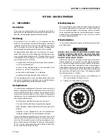
CYLINDER DRIFT TEST
Theory
When a hydraulic cylinder is supporting a load, cylinder drift
may occur as a result of any of the circumstances below:
• Normal leakage of load holding valves or malfunction of
load holding valves. See Cylinder Leakage Test and Table 2-
2, Cylinder Drift below for evaluation.
• Damaged or worn piston seals.
• Normal thermal expansion or contraction of the hydraulic
oil within cylinders (See Cylinder Thermal Drift below).
The first two circumstances may result in cylinder movement
due to oil leaking out of the cylinder externally or by leaking
back to tank or due to oil leaking internally from one cylinder
chamber to the other.
Thermal expansion or contraction of oil in hydraulic cylinders
is a normal occurrence and does not result in oil leaking out of
the cylinder or leaking internally from one cylinder chamber
to the other. Thermal expansion or contraction is the tendency
for materials to change size in response to a change in
temperature.
Cylinder Leakage Test
Cylinder oil must be at stabilized ambient temperature
before beginning this test.
Measure drift at cylinder rod with a calibrated dial indicator.
In an area free of obstructions, cylinder must have load
applied and appropriately positioned to detect drift.
Cylinder leakage is acceptable if it passes this test.
Cylinder Thermal Drift
The oil in all hydraulic cylinders will expand or contract due to
thermal effects over time and may result in changes to the
boom and/or platform position while the machine is station-
ary. These effects occur as the cylinder oil changes tempera-
ture, usually from a higher oil temperature as it cools and
approaches the ambient air temperature. Results of these
effects are related to several factors including cylinder length
and change in temperature over the time the cylinder remains
stationary.
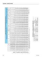
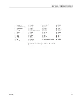
Table 2-2. Cylinder Drift
Cylinder Bore Diameter
Max. Acceptable Drift
in 10 Minutes
inches
mm
inches
mm
3
76.2
0.026
0.66
3.5
89
0.019
0.48
4
101.6
0.015
0.38
5
127
0.009
0.22
6
152.4
0.006
0.15
7
177.8
0.005
0.13
8
203.2
0.004
0.10
9
228.6
0.003
0.08
NOTE:
This information is based on 6 drops per minute cylinder
leakage.
Содержание 740AJ
Страница 1: ...Service and Maintenance Manual Model 740AJ Prior to S N 0300185827 P N 3121160 October 24 2017 AS NZS...
Страница 2: ......
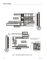
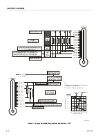
Страница 51: ...SECTION 2 GENERAL 3121160 2 11 Figure 2 2 Engine Operating Temperature Specifications Ford 4150548 E...
Страница 55: ...SECTION 3 CHASSIS TURNTABLE 3121160 3 3 This page left blank intentionally...
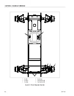
Страница 56: ...SECTION 3 CHASSIS TURNTABLE 3 4 3121160 1 Figure 3 2 Axle and Steering Installation Sheet 1 of 2 0258286 C...
Страница 100: ...SECTION 3 CHASSIS TURNTABLE 3 48 3121160 Figure 3 37 Swing Bearing Tolerance Boom Placement Sheet 1 of 2...
Страница 101: ...SECTION 3 CHASSIS TURNTABLE 3121160 3 49 Figure 3 38 Swing Bearing Tolerance Boom Placement Sheet 2 of 2...
Страница 116: ...SECTION 3 CHASSIS TURNTABLE 3 64 3121160 Figure 3 44 Swing Hub Prior to SN 0300074383...
Страница 124: ...SECTION 3 CHASSIS TURNTABLE 3 72 3121160 Figure 3 45 Swing Drive Hub Fairfield SN 0300074383 through 0300134352...
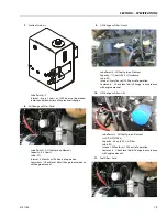
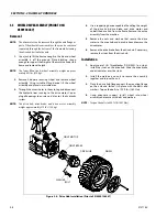
Страница 180: ...SECTION 3 CHASSIS TURNTABLE 3 128 3121160 1 Figure 3 66 Auxiliary Pump Location 1 AuxiliaryPump 2 HydraulicTank...
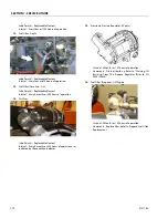
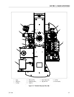
Страница 203: ...SECTION 3 CHASSIS TURNTABLE 3121160 3 151 Figure 3 77 EFI Component Location...
Страница 206: ...SECTION 3 CHASSIS TURNTABLE 3 154 3121160 Figure 3 78 ECM EPM Identification ECM EPM...
Страница 213: ...SECTION 3 CHASSIS TURNTABLE 3121160 3 161 Megajector Regulator LockoffSolenoid Figure 3 80 LPG System Components Mixer...
Страница 219: ...SECTION 3 CHASSIS TURNTABLE 3121160 3 167 Figure 3 81 Check Out and Initial Start Up Procedures...
Страница 224: ...SECTION 3 CHASSIS TURNTABLE 3 172 3121160 Figure 3 83 Deutz EMR 2 Troubleshooting Flow Chart...
Страница 225: ...SECTION 3 CHASSIS TURNTABLE 3121160 3 173 Figure 3 84 Deutz EMR 2 Vehicle Side Connection Diagram...
Страница 226: ...SECTION 3 CHASSIS TURNTABLE 3 174 3121160 Figure 3 85 Deutz EMR 2 Engine Side Connection Diagram Sheet 1 of 2...
Страница 227: ...SECTION 3 CHASSIS TURNTABLE 3121160 3 175 Figure 3 86 Deutz EMR 2 Engine Side Connection Diagram Sheet 2 of 2...
Страница 228: ...SECTION 3 CHASSIS TURNTABLE 3 176 3121160 Figure 3 87 EMR 2 Engine Plug Pin Identification...
Страница 229: ...SECTION 3 CHASSIS TURNTABLE 3121160 3 177 Figure 3 88 EMR 2 Vehicle Plug Pin Identification...
Страница 230: ...SECTION 3 CHASSIS TURNTABLE 3 178 3121160 Figure 3 89 EMR2 Fault Codes Sheet 1 of 5...
Страница 231: ...SECTION 3 CHASSIS TURNTABLE 3121160 3 179 Figure 3 90 EMR2 Fault Codes Sheet 2 of 5...
Страница 232: ...SECTION 3 CHASSIS TURNTABLE 3 180 3121160 Figure 3 91 EMR2 Fault Codes Sheet 3 of 5...
Страница 233: ...SECTION 3 CHASSIS TURNTABLE 3121160 3 181 Figure 3 92 EMR2 Fault Codes Sheet 4 of 5...
Страница 234: ...SECTION 3 CHASSIS TURNTABLE 3 182 3121160 Figure 3 93 EMR2 Fault Codes Sheet 5 of 5...
Страница 303: ...SECTION 4 BOOM PLATFORM 3121160 4 31 Figure 4 20 Rotator Assembly HELAC...
Страница 335: ...SECTION 4 BOOM PLATFORM 3121160 4 63 THIS SENSOR ON NON ADE MACHINES ONLY Figure 4 27 UMS Sensor Location...
Страница 336: ...SECTION 4 BOOM PLATFORM 4 64 3121160 Figure 4 28 UMS Module Location ADE MACHINES NON ADE MACHINES...
Страница 425: ...SECTION 5 BASIC HYDRAULIC INFORMATION AND SCHEMATICS 3121160 5 81 Figure 5 131 Variable Displacement Pump Rexroth...
Страница 443: ...SECTION 5 BASIC HYDRAULIC INFORMATION AND SCHEMATICS 3121160 5 99 Figure 5 146 Fault Logic Troubleshooting...
Страница 444: ...SECTION 5 BASIC HYDRAULIC INFORMATION AND SCHEMATICS 5 100 3121160 Figure 5 147 Fault Logic Troubleshooting...
Страница 445: ...SECTION 5 BASIC HYDRAULIC INFORMATION AND SCHEMATICS 3121160 5 101 Figure 5 148 Fault Logic Troubleshooting...
Страница 460: ...SECTION 5 BASIC HYDRAULIC INFORMATION AND SCHEMATICS 5 116 3121160 NOTES...
Страница 467: ...SECTION 6 JLG CONTROL SYSTEM 3121160 6 7 Figure 6 2 ADE Block Diagram...
Страница 471: ...SECTION 6 JLG CONTROL SYSTEM 3121160 6 11 Figure 6 6 Analyzer Flow Chart Prior to Version 5 X Software Sheet 4 of 4...
Страница 473: ...SECTION 6 JLG CONTROL SYSTEM 3121160 6 13 Figure 6 8 Analyzer Flow Chart Version 5 X Software Sheet 2 of 4...
Страница 534: ...SECTION 6 JLG CONTROL SYSTEM 6 74 3121160 NOTES...
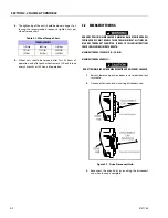
Страница 545: ...SECTION 7 BASIC ELECTRICAL INFORMATION SCHEMATICS 3121160 7 11 Figure 7 15 Connector Installation...
Страница 580: ...SECTION 7 BASIC ELECTRICAL INFORMATION SCHEMATICS 7 46 3121160 NOTES...
Страница 581: ......


