JL Audio VX1000/5i Скачать руководство пользователя страница 11


 | 

Page 8

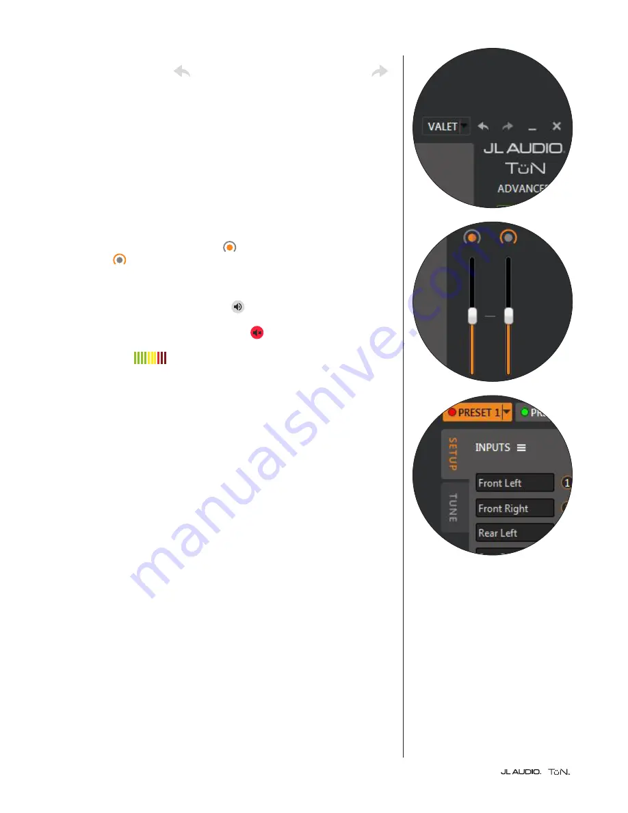
At the top right of the TüN™ interface’s dark gray frame you will find  
UNDO/REDO: a left facing 

 (UNDO) arrow and a right facing (REDO) 


arrow. As you have probably figured out, these allow you to retrace your tuning 

steps and come back, one-by-one.

The rest of the right vertical edge of the dark gray frame is dedicated to status 

indicators and for TwK™ user controls needed while connected to the PC.

Below the JL AUDIO TüN™ logo, you will see a display of the current Project 

Level (Basic, Advanced or Expert). Below that, you will find connection  

status indicators.

TwK™ CONTROLS: These controls talk to the TwK™ hardware directly, 

without any permanent effect on the current Preset or Project. Since the 

DRC is disabled when the PC is connected via USB, the two VERTICAL 

SLIDER controls become your volume  


(inner DRC knob) and secondary 

level control  


(outer DRC knob), while tuning with your PC. When you 

disconnect the PC, the TwK™ will immediately revert to being controlled by the 

DRC connected to it.

Below the sliders is the MASTER MUTE 


button to mute/unmute all  

TwK™ outputs. Below the Master Mute, you will find individual CHANNEL 

MUTE


buttons. The mute buttons display red 


when muted. These are useful 

for isolating channels while tuning or for troubleshooting purposes. SIGNAL 

LEVEL METERS        for each output channel are located next to the 

Channel Mute buttons. 

PRESET CONTROL AREAS

Now that we’ve covered the features in the TüN™ software’s dark gray frame, we 

will focus on the light gray areas that house all of the data related to a currently 

selected PRESET. All parameters displayed in the light gray areas are stored 

within the selected PRESET. This means that you can create multiple PRESETs 

with variations of all these features, including the use of different inputs, different 

outputs, more or fewer EQ banks, different signal routing, different crossovers, 

etc. The configuration for each PRESET is organized in two Tabs, located at the 

upper left of the TüN™ interface. These are labeled “SETUP” and “TUNE”.

Содержание VX1000/5i

Страница 1: ... and Subwoofer Output Connector To connect the power ground remote turn on and subwoofer output wires to the amplifier back out the set screws on each connector using the supplied hex wrenches Strip back 3 8 inch 10 mm of insulation from the end of each wire and insert the bare wire into the receptacle on the power connector plug seating it firmly so that no bare wire is exposed While holding each...

Страница 2: ...Negative Subwoofer Output Data Connections Label Type Description Use JLid COMM RJ45 Jack Optional accessory connections VXi BTC VXi HUB etc JLid CTRL RJ45 Jack Optional DRC Digital Remote Controller connection USB USB A B Port Computer connection to configure TüN Software Interface DIGITAL In S PDIF Port 2 channel optical Toslink digital input DIGITAL Out S PDIF Port 2 channel optical Toslink dig...

Страница 3: ......

Страница 4: ...Software Overview for use with TwK Processors ver 2 0 ...

Страница 5: ...PERATING A MOTOR VEHICLE OR VESSEL TwK TüN SOFTWARE OVERVIEW TüN is JL Audio s DSP tuning software for the PC platform It has been developed to control and manage JL Audio DSP products TüN is designed to automatically recognize which product s it is connected to allowing you to select one at a time configuring its interface appropriately for that product While the TüN software is designed to work ...

Страница 6: ...which allows a PRESET to be enabled disabled renamed duplicated or deleted The Duplicate function allows you to create an exact copy of an existing PRESET which you can then modify without disturbing your previous PRESET You will also assign a color to each Enabled PRESET This color will be displayed on the DRC s LED when you activate that PRESET This permits the user to easily identify the PRESET...

Страница 7: ...ration 7 SETUP TAB CONFIGURATION Project Management 7 8 INPUTS Panel 8 9 INPUT MIXER Panel 9 EQUALIZERS Panel 9 ROUTER Panel 9 DRC SETUP Panel 10 OUTPUTS Panel 10 TUNE TAB CONFIGURATION EQUALIZERS Panel 11 12 CROSSOVERS Panel 12 13 DELAY POLARITY Panel 14 OUTPUTS Panel 14 15 Workspace Legend Page NEW PROJECT CONFIGURATION ...

Страница 8: ...Page 5 SETUP TAB CONFIGURATION TUNE TAB CONFIGURATION ...

Страница 9: ...Output Polarity 10 band Graphic Equalizers High Pass and Low Pass Filters 12 24 or 48 dB octave Linkwitz Riley and Level Trim controls Advanced offers a full feature set with restrained safeguards to prevent accidental damage to the audio system This is ideal for experienced DSP users looking to get full advantage of the TwK s power while avoiding certain pitfalls that can result in poor performan...

Страница 10: ...can be selected in the Preferences menu if preferred The TüN software will automatically convert these distance numbers to delay parameters If you do not wish to apply speaker distance compensation in your starting configuration simply skip this step PLEASE NOTE ALL PARAMETERS SET WITH THE SETUP TOOL CAN BE EDITED LATER IN THE SETUP AND TUNE TABS OF THE TÜN SOFTWARE PROJECT MANAGEMENT Settings and...

Страница 11: ...connect the PC the TwK will immediately revert to being controlled by the DRC connected to it Below the sliders is the MASTER MUTE button to mute unmute all TwK outputs Below the Master Mute you will find individual CHANNEL MUTE buttons The mute buttons display red when muted These are useful for isolating channels while tuning or for troubleshooting purposes SIGNAL LEVEL METERS for each output ch...

Страница 12: ...e EQ Banks and has the ability to combine input channels It uses an intuitive clickable interface that provides visual feedback of input signal routing In Advanced and Expert modes additional mixing flexibility is enabled by permitting input polarity and relative level to be adjusted to create spatial effects Pre EQ Level Trim Allows the output levels of the mixer to be reduced as much as 12 dB pr...

Страница 13: ... outputs of the EQ Banks and the Output Channels Like the Input Mixer the Router uses an intuitive clickable interface that provides visual feedback of output signal routing DRC SETUP Panel This panel allows you to configure the behavior of the DRC 200 that is included with the TwK Check boxes allow you to determine which channels will be controlled by the inner and outer knobs of the DRC 200 By c...

Страница 14: ...EQ mode Q The shape of the EQ filter response Lower Q values result in wider bandwidth EQ filter response Higher Q values result in narrower bandwidth EQ filter response This value is fixed in Graphic EQ mode and variable in Parametric EQ mode from 0 26 to 10 Default value is 1 41 Gain The amount of amplitude boost or cut applied through the selected filter expressed in decibels and adjustable fro...

Страница 15: ...aphic and Parametric EQ modes when in the Advanced or Expert Project Levels IMPORTANT YOU MAY SWITCH FROM GRAPHIC TO PARAMETRIC MODE WITHOUTLOSINGANYSETTINGS BUTSWITCHINGFROMPARAMETRICTO GRAPHIC MODE RESETS THE PRESET S EQ BANKS TO DEFAULT SETTINGS CROSSOVERS Panel The following controls are available for each Output Channel A few definitions of crossover terms High Pass Filter uniformly allows si...

Страница 16: ...e above plus 6 dB per octave and 12 18 24 36 48 dB per octave Butterworth alignment BW Some basic guidelines for setting filter frequencies and good starting frequencies for tuning a system use 24 dB octave L R slope 2 way System Coaxial Component System with passive crossover between woofer and tweeter 80 Hz High Pass Subwoofer 80 Hz Low Pass 3 way System Tweeter 5000 Hz High Pass Component woofe...

Страница 17: ...itions in the vehicle by creating a PRESET for each one and entering the appropriate values Additional Delay Here you can add delay to the baseline delay correction Clicking the arrows moves the value approximately 0 2 ms Holding the Shift key while clicking the arrows results in a step value of 0 02 ms which is the minimum delay step value Any entered values will be rounded up to the nearest avai...

Страница 18: ...TE AND IS NOT SAVED IN THE PROJECT FILE Appendix A Twk Input Sensitivity Level Setting Selecting the appropriate Input Sensitivity setting is critical to achieving maximum low distortion output To properly set the TwK s Input Sensitivity settings perform the steps below prior to making any amplifier adjustments Necessary Equipment CD or file with a pink noise test track 1 After all wiring is compl...

Страница 19: ... Ahead of the Curve and the JL Audio logo are registered trademarks of JL Audio Inc 2017 JL Audio Inc For more detailed information please visit us online at www jlaudio com Due to our policy of continuous product development all specifications are subject to change without notice 03 13 17 ...

Отзывы: