User’s Manual
27
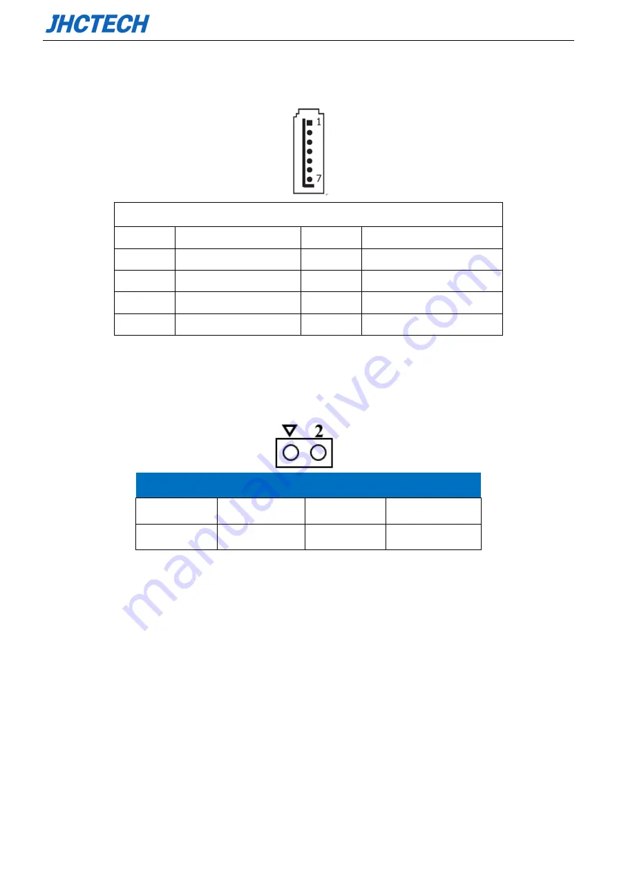
2.3.21 Serial ATA1(S_SATA1)
Table 2.22
:
Serial ATA1 pin assignments
Pin
Signal
Pin
Signal
1
GND
5
RX-
2
TX+
6
RX+
3
TX-
7
GND
4
GND
2.3.22 COMS battery connector (BAT1)
Table 2.23
:
CMOS battery connector pin assignments
Pin
Signal
Pin
Signal
1
BAT+
2
GND
2.4 Installation
2.4.1 Install/replace HDD/SSD
Step 1: Unscrew the 5 screws on the hard disk cover, and then remove the hard disk cover.
Содержание PADR-M101
Страница 1: ...用户手册 PADR M101 User s Manual Ver A0 1 Date 2021 08 09 ...
Страница 2: ...User s Manual 版本信息 No Ver Note Date Writer 审核 1 A0 1 first publish 2021 8 9 Eva Li Jesse Chen ...
Страница 9: ...User s Manual 1 General Information 1 CHAPTER ...
Страница 14: ...User s Manual 6 Figure 1 1 SBC ECM I910 Rear view Figure 1 2 Expansion power module OFX 075 ...
Страница 15: ...User s Manual 7 Figure 1 3 Expansion adapter ECD 9100 Figure 1 4 PADR M101 Dimension Unit mm ...
Страница 16: ...User s Manual 8 Figure 1 5 Unit mm ...
Страница 17: ...User s Manual 9 Hardware Installation 2 CHAPTER ...
Страница 19: ...User s Manual 11 Figure 2 2 Jumper and Connector Location Figure 2 3 I O Connector ...
Страница 44: ...User s Manual 36 BIOS Setup 3 CHAPTER ...
Страница 58: ...User s Manual 50 Figure 3 14 North Bridge Scroll to this item and press Enter and view the following screen ...
Страница 66: ...User s Manual 58 5 To prevent accidents please backup the current BIOS data first ...
Страница 67: ...User s Manual 59 SYSTEM RESOURCE CHAPTER 4 ...


