background image

Baby Lock Jewel Service Manual 

© Baby Lock, all rights reserved 


22

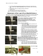
Rotating basket down

 - 

Note:  With the bobbin 

case basket in the normal position, the basket 
needle guard deflects the needle and makes it 
difficult to accurately adjust the needle distance 
between the hook point and the back of the 
needle scarf.  It is important that the basket 
needle guard be rotated down out of the way to 
allow correct adjustment of the needle distance 
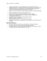
setting. Figure 38 shows the stop finger 
engaged with the bobbin case, installed from 
down below. 


Stop finger engaged with bobbin case installed 
from below. Figure 38 


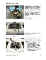
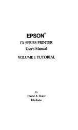
Stop finger engaged without bobbin case from 
above – Figure 39 


Rotate the basket out of the way to facilitate the 
needle distance adjustment 

- Important:  after 

moving stop finger you need to hold basket 
in place when turning hand wheel to prevent 
needle from hitting basket. 


Loosen the stop finger screw with the


(2.5mm handle Allen tool). 


Slide the stop finger out of the basket 
groove, until the basket can be rotated.  


Snug the stop finger screw. 


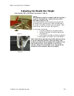
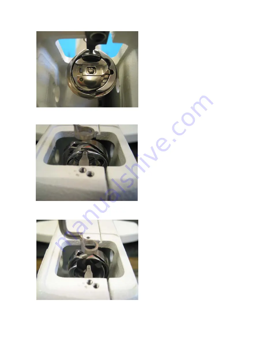
Rotate the basket 180 degrees until 
large cutout is up towards needle as 
shown in figure 40

 (you will now need 

to hold the basket in that position - 
see important note above)


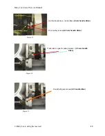
Figure 38 

Figure 39 

Figure 40 

Содержание Baby Lock

Страница 1: ...Baby Lock Service Manual Provisional...

Страница 2: ...axis 20 Adjustment of the Loop Lift and Needle Distance 21 Adjusting the Needle Bar Height 23 Adjustment of the Stop Finger 24 Adjusting the Needle Height with Cylinder Tool 25 Needle Height with Cyli...

Страница 3: ...ossible Misunderstandings 36 Setup and Mechanical Problems 36 Operation Problems 37 Stitch Regulator Methodical Check 38 Stitch Regulator Trouble shooting 39 Setup Errors 39 Operation Errors 39 Mechan...

Страница 4: ...is to help the technician complete a repair on a machine accurately and quickly The manual is complete with photographs and explanations that we hope will aid you in your repair efforts In addition to...

Страница 5: ...oke 35 3 mm Take Up Stroke 73 mm Assembly Torque Specification The Torque Specifications apply to all internal fasteners in sizes 4 0 5 0 and 6 0mm in general at ISO 4762 Screw class 8 8 The torque sp...

Страница 6: ...resuming the sewing of the quilt Failure to do so may result in oil stains on the quilt piece General Observation of the Front Frame Cover Mast and Hand Wheel The following observations accompanied b...

Страница 7: ...en the frame boss and the back disk of the tension assembly see figure 1 4 If a correction is necessary loosen screw 2mm handle Allen adjust the gap between the front cover and the rear tension disk a...

Страница 8: ...and the P Pod are STATIC SENSITIVE parts and should not be handled without special discharge tools For this reason all C and P Prints will be exchanged in the pod covers Do not remove the Printed Circ...

Страница 9: ...A in Figure 6 rotate the thread guide to allow access to the frame screw then re snug 2mm handle Allen tool 2 Remove the three frame screws as shown in Figure 7 3mm handle Allen tool 3 Remove the C p...

Страница 10: ...the 5 frame screws D in Figure 11 Note The fifth screw is behind the C print removed in step 4 4mm handle Allen may need 4mm L Allen tool to break loose screws 7 Separate the Front Frame Cover Make s...

Страница 11: ...Baby Lock Jewel Service Manual Baby Lock all rights reserved 11 Machine Cross Section...

Страница 12: ...is then tightened compounding the tightness of the first screw thus securing and assuring that timing will not change See Figure 12 Note See torque specifications chart in the specification section fo...

Страница 13: ...Lock all rights reserved 13 Figure 16 Hand wheel screw inside frame 3mm handle Allen Drive pulley screws 2 5mm handle Allen Transmission gear pulley screws 2 5mm handle Allen Hookshaft gear screws 2...

Страница 14: ...visionally set the first screw tighten the second screw fully tight Tighten the first screw 2 Check the transmission shaft by pushing and pulling axially on the gear as shown in Figure 20 If a correct...

Страница 15: ...he rubber feet will sit flat on a planed surface If a correction is necessary 0 012 shim washers may be used as shown in Figures 23 and 24 Adjustment of Base Plate Rollers The base plate rollers must...

Страница 16: ...he main timing belt See Figure 26 Check the belt tension for tautness by pressing it with the index finger see Figure 26 Proper belt tension provides for some belt flexibility under light finger press...

Страница 17: ...two gears If correction is necessary Loosen the two screws in the elongated slots on the transmission housing above the gear 4mm Allen tool Adjust the transmission mount with elongated slots up for mo...

Страница 18: ...feel play between the belt teeth and the transmission timing pulley teeth NOTE if you tighten the belt too much you will create a bind or extra noise in the machine If a correction is necessary Loosen...

Страница 19: ...pping foot Figure 28 Loosen screw C through the machine front cover 3mm Allen driver Figure 29 Rotate the presser bar while raising the presser bar up or down to the desired position Tighten screws C...

Страница 20: ...t adjustment is done with the front frame cover off Loosen first the screws G and D in figure 33 3mm handle Allen Loosen screws A and B in figure 32 3mm handle Allen While pushing the head frame back...

Страница 21: ...he needle bar is at its lowest position or BDC Place the loop lift clamp special protective clamp on the needle bar and set the thumbscrew lightly Place the 2 2mm feeler gauge between the clamp and th...

Страница 22: ...down below Stop finger engaged with bobbin case installed from below Figure 38 Stop finger engaged without bobbin case from above Figure 39 Rotate the basket out of the way to facilitate the needle di...

Страница 23: ...should be 1 0mm above the top of the needle eye See figure 41 If a correction is necessary Lower the needle bar to its highest position Insert a screw driver through the access hole See figure 42 Loo...

Страница 24: ...upport basket must have a clearance of 0 8mm to 1 0mm This clearance ensures that adequate space exists for thread escapement during the sewing process If an adjustment is necessary Loosen screw A in...

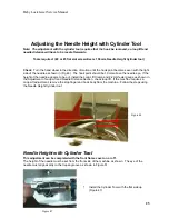
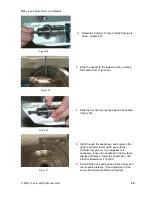
Страница 25: ...1 0mm above the needle eye If the height of the needle appears to be out install the Loop Lift Clamp and 2 2mm feeler gauge as shown in the Adjustment of Loop Lift and Needle Distance Section check l...

Страница 26: ...the needle Figure 50 5 Sight through the needle eye and compare the upper and lower levels of the eye with the Cylinder tool groove If an adjustment is necessary loosen the needle bar driving clamp s...

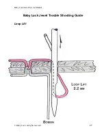
Страница 27: ...Baby Lock Jewel Service Manual Baby Lock all rights reserved 27 Baby Lock Jewel Trouble Shooting Guide Loop Lift...

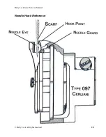
Страница 28: ...Baby Lock Jewel Service Manual Baby Lock all rights reserved 28 Needle Hook Reference...

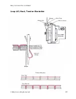
Страница 29: ...Baby Lock Jewel Service Manual Baby Lock all rights reserved 29 Loop Lift Hook Tension Illustration...

Страница 30: ...arped bobbin from winding too tight pretension set too tight Foundation bottom like a house foundation crack story it will never be right until the foundation is corrected or the true cause of the pro...

Страница 31: ...make the machine seem inconsistent Some things to check Visual checks of the top tension assembly The gray knob has a round dot to help determine how much the knob is turned A starting point for the...

Страница 32: ...oving the machine over fabric held in place on the frame it is possible to pull or push the thread under the needle thereby sewing over or into the thread The needle point actually hits and pierces th...

Страница 33: ...ric properly it will be strong and nice looking because the knots will be locked up in the fabric with proper friction Four major causes of skipped stitches Improper loop formation out of time poor fr...

Страница 34: ...on the controls The motor speed is then controlled only by your movement speed The faster you move the faster the machine sews The slower you move the slower the machine sews If you move too slow the...

Страница 35: ...lt too fast the stitch regulator will not perform as the operator desires The more stitches per inch the operator selects the slower the operator will be able to move across the quilt because the mach...

Страница 36: ...n mode works best when the operator is smooth and consistent Possible Misunderstandings Misunderstanding that One can move the machine any speed and the machine will do the same size stitch in Regulat...

Страница 37: ...ncoder bracket bent by sliding the machine sideways Rear machine encoder stop bent down holding wheel up off carriage track Carriage encoder bracket bent Small rubber wheel not riding on bottom plasti...

Страница 38: ...ine will do if they just stop moving in Regulated Mode It will also be about 3 or 4 Make sure they understand why the machine sews a few more stitches if they just stop moving the machine and that if...

Страница 39: ...operly Operation Errors Ran over encoder cable with the machine metal wheel before connecting it Moving too fast or slow or with too much irregularity or quick speed variations Did not hit select the...

Страница 40: ...s Select to toggle back and forth between needle up and needle down Set for Needle Down Stitch Half Full Programs the needle to take a half or full stitch when the Needle Up Down button on the handleb...

Страница 41: ...would be 750 SPM The speed easy to over ride when you are in Manual Mode by using Speed Up or Speed Down on the handlebars Set the speed for 70 1050 SPM Select Returns to Set Up menu Light Mode Press...

Страница 42: ...l the time Set to On Exit Menu Press Select to Exit Walking and return to Set up Quilt Mode Press Select to Exit set up menu NOTE Anytime you need a quick exit out of the Set Up menu just press the Ne...

Отзывы: