JETWAY FFI02 Series Скачать руководство пользователя страница 6

6

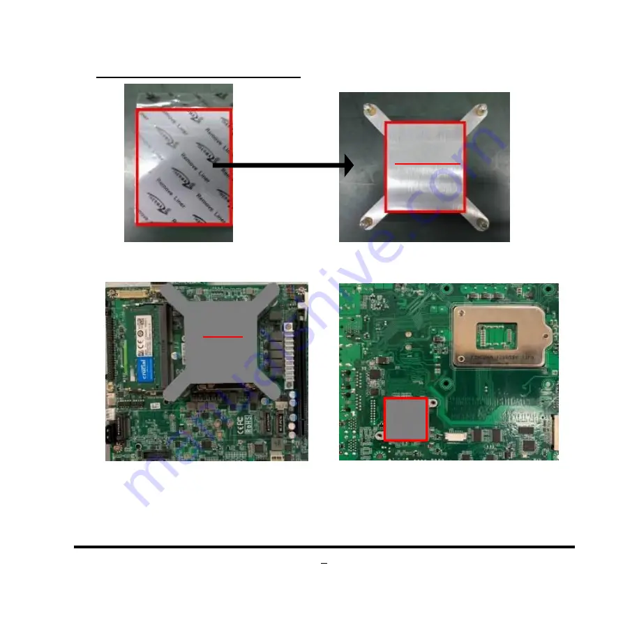
III.To Install Heatsink Thermal pads

1. Find the above CPU heatsink and CPU thermal pad package. Remove the protective films

on the both sides of the pad and apply it upon the bottom side of the heatsink for better heat

conduction.

2. Place the CPU heatsink upon the

installed CPU. The screw holes of the

heatsink should match corresponding

screw holes of the board. And then apply

corresponding thermal pad to the top

side of the heatsink as the photo shows.

3. Apply corresponding thermal pads to chipset

heat

sink

(HCS3XXHS2-F*2pcs).

When

installation finished, tear off the protective film

from the pads before assembling the back cover

to the chassis.

Bottom Side

Paste Here!

Top Side

Paste Here!

Tear off the

Protective films

P/N:

HCS310HS1-F* 2pcs

60*52*1.0mm

Содержание FFI02 Series

Страница 1: ...de NO G03 FFI02QIG F Rev 1 0 Release date 2021 12 13 Notice The photos in this file are for illustration purpose only The model may not be the latest version Please refer to the product you purchased...

Страница 2: ...rked on the top cover of the system and unscrew them one by one 2 Turn over the bare bone system with the heatsink upwards as the photo shows 3 Remove the screws in the marked spots on the front panel...

Страница 3: ...remove the screws on the marked spots to dissemble the motherboard form chassis cover Notice 1 If the system is pre installed with CPU heatsink user needs to remove the screws on the backside of the...

Страница 4: ...emove the plastic protective cover from the socket Put it to the original place if CPU is not installed Do not touch the metal contact pins of the CPU socket 3 Press down the level and move it towards...

Страница 5: ...with two points of the socket CPU can only be correctly installed in this direction Incorrect installation might cause damage to CPU 6 Put down the load plate in the direction shown above 7 Press dow...

Страница 6: ...PU The screw holes of the heatsink should match corresponding screw holes of the board And then apply corresponding thermal pad to the top side of the heatsink as the photo shows 3 Apply corresponding...

Страница 7: ...lock the heatsink to the board by tightening the screws P N LCSC378M01 F 4 on the marked spots 5 Thermal pads need to be attached to the bottom of the motherboard which will help the system to dissipa...

Страница 8: ...sponding damaged thermal conductive pads Notice Please restore the screws that lock the motherboard to the chassis cover when CPU heatsink installation completed The cables unplugged during this proce...

Страница 9: ...patible SO DIMM into the slot at a 30 degree angle See to it that the break of the module fit into the notch of the slot 3 Press down to secure the SO DIMM to the slot The eject tabs will lock automat...

Страница 10: ...Remove the marked screw nut reserved for M 2 PCIe card installation first 3 Insert the gold figure side of compatible card into M 2 PCIe slot See to it that the golden figure side is fully inserted i...

Страница 11: ...enna as the following details show a Back side View Put the metal ring into the antenna head at first and then push this antenna head into antenna hole of the rear panel b Front side View Put the othe...

Страница 12: ...avoid possible damage to the system 7 Tear off the tape to find metal hats of Wi Fi antenna string 8 Press the metal hat on the end of the antenna string to the antenna slot on the card as shown 9 Con...

Страница 13: ...slot until the golden finger side fully emerged into the slot 4 Install the screw back to the original spot Note the screw post and nut fixed at location MH1 by default for 4 2cm type 3042 card instal...

Страница 14: ...M Key type 2280 slot on the board 2 Remove the marked screw with a screwdriver 3 Insert the gold figure side of compatible M 2 2280 card into the slot until the golden finger side fully emerged into...

Страница 15: ...15 VIII To Install Hard Disk 1 Remove the screws in the marked spots on the front panel 2 Lock the SATA hard disk to one of the racks by tightening the screws in the marked spots...

Страница 16: ...16 3 Lock the SATA hard disk to the other rack by tightening the screws in the marked spots 4 Insert the gold figure side of the compatible STAT HDD into the slot...

Страница 17: ...17 5 Install the screw back to the original spot 6 Find the compatible SATA cable for the system in the accessories package...

Страница 18: ...ck the racks with SATA HDD installed connector and SATA connector of the hard disk to its original places by tightening the screws in the marked spots 9 Plug the other sides of the cables into the SAT...

Страница 19: ...ng the back cover to the chassis and screws on the front panel back panel top cover locked to its original places Refer to Part I See to it that the cables inside are not blocked or pressed IX To Wall...

Страница 20: ...20 2 Wall mount the system by tightening two screws in the marked positions Then tighten up the other two screws in the marked positions on the other rack...

Отзывы: