


Jetter AG
Technical specifications | 4
jxm-io-ew30_ba_2151_manual
16 / 56
4.6.1 Current diagnostics at the outputs
Outputs DO_H3 and PWM_H7 use the internal resistor (RDSon) of the output
driver for current measurement. The PWMi_H3 outputs have their own shunt re-
sistor with measuring amplifier. All outputs are calibrated at the factory to achieve
the highest possible accuracy. For low current values the measurement is not lin-
ear. The measurement is therefore linearized by the firmware:
T1
T2
A
B
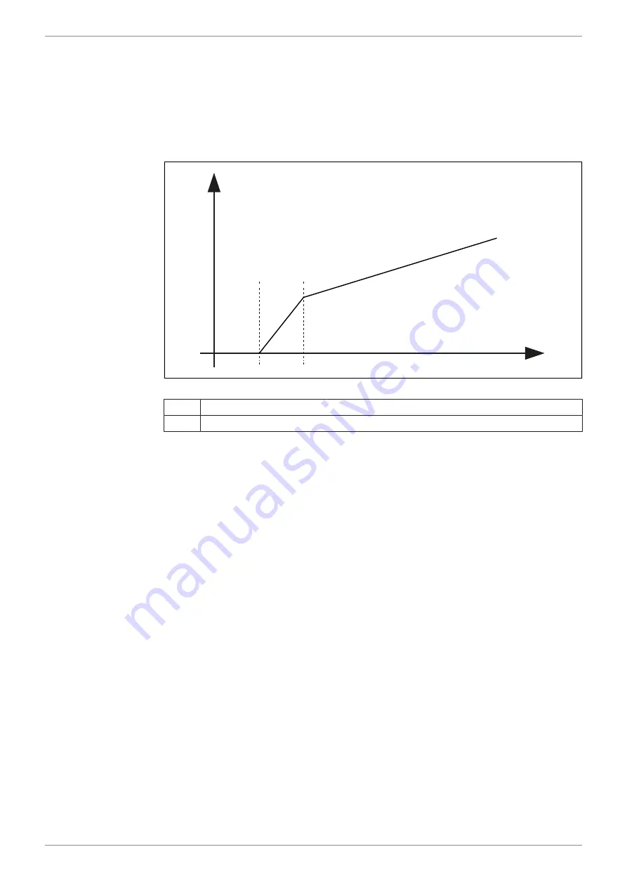
Fig. 4:
Graph: Principle of linearization
A
Current value
B
ADC value
T1 is 200 mA. Current below this value is displayed as 0.
T2 is 500 mA. From 500 mA to 200 mA the measured current value is linearized.
4.6.2 Overcurrent shutdown at outputs
If overcurrent flows through an output for 500 ms (default value), the overcurrent
shutdown becomes active. This value can be changed using the parameter
OVERCURRENT_TIME. If an overcurrent event occurs, the output shuts down
and the overcurrent bit is set for 10 seconds. During this time the port cannot be
switched on again.
Re-enabling the
port
ü
You are in OPERATIONAL mode.
ü
You waited 10 seconds after the output switched off.
►
Set the output value (digital or PWM) of the respective port again.
4.7 Inputs
Within the operating voltage range, all inputs are voltage-proof and overcurrent
protected. The JXM-IO-EW30-G27 has 3 separate VEXT_SEN connector pins
which should be used to supply the sensors. The connector pins output the bat-
tery voltage via a PTC thermistor. The output voltage can be read back in the de-
vice so that a failure of the sensor supply can be detected.
Alternatively, the analog inputs can also be used as digital inputs (DI_PNP).