


2.4
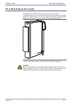
Mounting wall-mount devices
Step
Action
Comment
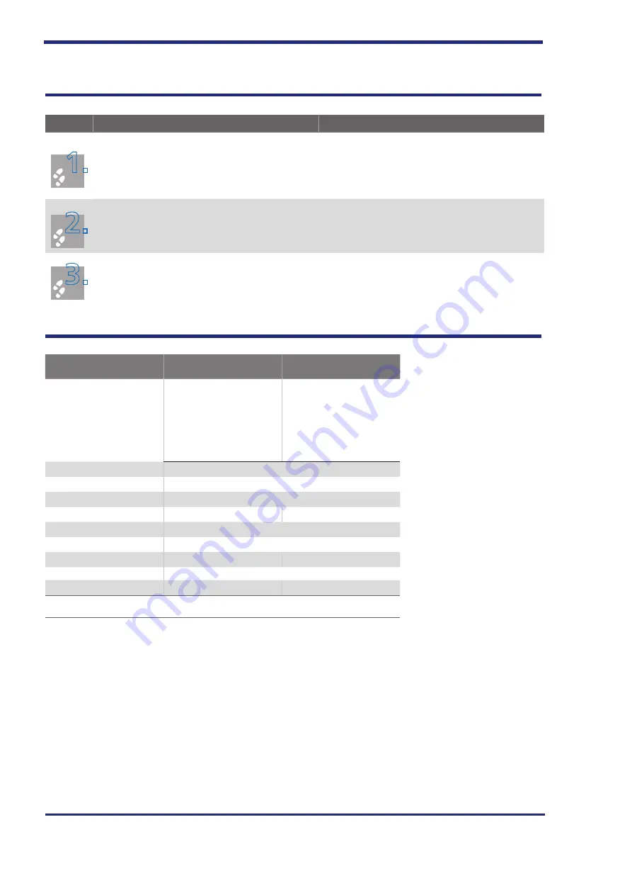
1
1
.
.
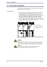
Arrange the units on the mounting plate as shown
Align all devices of the multi-axis system in one
line along the upper edge of the device.
This is necessary to be able to connect the DC link
busbars.
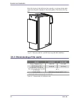
2
2.
Mark off the positions of the mounting holes on the
mounting plate.
Drill the holes into the mounting plate and tap a
thread for each fastening screw.
Take into account the bending radii of the connec-
tion cables!
For hole spacings and dimensional drawings see
Table 2.1, Fig. 2.4 and Fig. 2.5.
3
3.
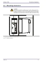
Mount the servo amplifiers vertically on the mount
-
ing plate and in a row with the supply unit.
The contact surface must be bare metal and con-
ductive.
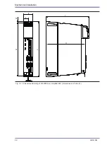
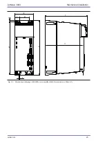
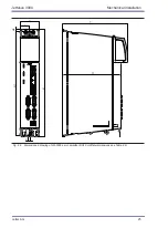
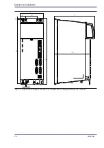
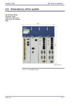
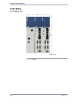
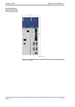
2.4.1
Dimensions of the version for wall mounting
JM-3000
BG1
BG2
Weight
JM-D3503 - 2.6 kg
JM-T3503 - 2.8 kg
JM-3506 - 2.6 kg
JM-D3506 2.75 kg
JM-T3506 - 2.8 kg
JM-3512 - 2.7 kg
JM-3518 - 2.7 kg
JM-D3512 - 4.3 kg
JM-T3512 - 4.5 kg
JM-D3516 - 4.3 kg
JM-3524 - 4.5 kg
JM-3532 - 4.5 kg
H (height)
1)
310
H1
299
H2
6
W (width)
55
110
D (depth)
241
T1
222
A
27.5
27.5
Lateral distance
Can be lined up without gap
C (screws)
2 x M4
4 x M4
All dimensions in mm
Drawing see Fig. 2.3 and Fig. 2.5
Table 2.1 Dimensions and mounting distances
Jetter AG
21
JetMove 3000
Mechanical installation
Содержание JetMove 3000
Страница 1: ...We automate your success User Manual JetMove 3000 Servo Amplifier 608880297...
Страница 30: ...JM 3000 Example supply unit with two servo amplifiers BG1 Fig 2 11 JM 3000 Mechanical installation 30 Jetter AG...
Страница 32: ...Mechanical installation 32 Jetter AG...
Страница 70: ...70 Jetter AG...
Страница 74: ...Diagnostic functions 74 Jetter AG...
Страница 76: ...Standard version S1 76 Jetter AG...