Jet VBS-1408 Скачать руководство пользователя страница 10


10

far enough back to clear saw blade even 
during cutting operation when the blade is 
deflected toward the rear. 

3.  Tighten the two screws (G, Figure 8). 

4.  Open upper access door and rotate blade 

wheel by hand until weld portion of blade is 
between the two fingers. 

5.  Loosen two socket head cap screws (H, Figure 

8) and adjust each finger toward the blade. 
They should not touch the blade. Adjust for 
0.010” clearance on either side. 

6.  Retighten the two screws (H, Figure 8) once 

proper adjustment has been made. Be sure 
that adjustment for air nozzle has not changed 
and it directs the flow of air to the cut. 


Figure 8 

7.  Adjust lower blade guides in similar manner. 

Note: Even properly adjusted blade guides will 
show wear after continual use. Readjust as 
necessary. If the blade guides become difficult to 
adjust, switch the left and right blade guides. 
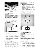
10.4

  Top guide adjustment 

Always position top guide to within 1/8” of the top 
surface of workpiece. This minimizes exposure of 
operator’s hands to the saw blade. 
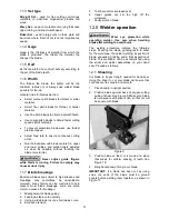
10.5

  Changing saw blades 

1.  Disconnect saw from power source. 

2.  Move upper blade guide to its highest position 

and lock in place. 

3. Open both wheel doors. Turn tension 

adjustment handwheel counterclockwise to 
loosen tension on blade. 

4. Remove blade from both wheels and 

maneuver it around blade guard on column 
and protective shield on upper blade guide. 

Use gloves when handling blades.


5.  Install new blade by maneuvering around 

blade guard on column and protective shield 
on upper blade guide. 

6.  Place it between the fingers of both blade 

guides and onto both wheels. Position next to 

both wheel flanges. Make sure teeth point 
down toward table. NOTE: If teeth will not 
point downward regardless of blade 
orientation, the blade is inside-out. Twist blade 
outside-in and reinstall. 

7.  Tension blade by turning tension handwheel. 

Rotate wheel by hand and make sure blade is 
properly seated in blade guides. Blade guides 
will have to be adjusted if the replacement 
blade is a different type and width. 

8.  Turn on saw and check blade tracking. Adjust 

tracking if necessary. 

10.6

  Work lamp bulb 

The work lamp uses a standard medium-base 60 
watt bulb (not provided). 
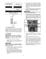
11.0

  Blade selection 

Proper blade selection is just as important to band 
saw operation as is blade speed and material feed.  
Proper blade selection will impact blade life, 
straightness of cut, cut finish, and efficiency of 
operation. Excessive blade breakage, stripping of 
teeth, and waviness of cut are some of the results 
of improper blade selection. 

Blades are classified by material composition, tooth 
shape, tooth pitch, tooth set, gage of the band 
material, and kerf of the set (width of cut). 

11.1

  Material composition  

Carbon Steel

 – low cost, for use with non-ferrous 

materials, wood, and plastics. 

High Speed Steel

 – resists heat generated by dry 

cutting.  Used for ferrous metals. 

Alloy Steel

 – tough and wear resistant, cuts faster 

with longer blade life. Used on hard materials.  
More expensive than carbon or high speed steel. 

Carbide Tipped

 – for cutting unusual materials 

such as uranium, titanium, or beryllium.  
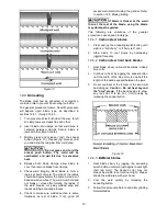
11.2

  Tooth shape 

Note

: When cutting thin materials, the rule for 

blade pitch is to have a minimum of two teeth 
engaging the material being cut at all times. 

Standard Tooth

 - generally used to cut ferrous 

metals, hard bronze, hard brass, and thin metals. 

Skip Tooth

 - have better chip clearance (larger 

gullet) and are used on softer, non-ferrous 
materials such as aluminum, copper, magnesium, 
and soft brass. 

Hook Tooth

 - provides a chip breaker and has less 

tendency to gum up in softer materials. Used in the 
same materials as skip tooth but can be fed faster 
than standard or skip tooth blades. 

Содержание VBS-1408

Страница 1: ...14 inch Metalworking Band Saw Model VBS 1408 WALTER MEIER Manufacturing Inc 427 New Sanford Road LaVergne Tennessee 37086 Part No M 414483 Ph 800 274 6848 Revision G 04 2013 www waltermeier com Copyri...

Страница 2: ...ge prepaid to a location designated by us For the name of the location nearest you please call 1 800 274 6848 You must provide proof of initial purchase date and an explanation of the complaint must a...

Страница 3: ...breakage 11 12 0 Welder operation 11 12 1 Shearing 11 12 2 Removing Teeth 12 12 3 Welding 12 12 4 Annealing 13 12 5 Blade grinding 14 12 6 Secondary Annealing 14 12 7 Welder Clean Up 14 13 0 Band saw...

Страница 4: ...masks that are specifically designed to filter out microscopic particles 10 Do not operate this machine while tired or under the influence of drugs alcohol or any medication 11 Make certain the switch...

Страница 5: ...pieces carefully keeping hands away from the blade The saw must be stopped and the electrical supply cut off or machine unplugged before reaching into the cutting area 37 Don t use in dangerous enviro...

Страница 6: ...height from floor at 90 39 Table tilt Front and Back 8 deg Right 15 deg Left 12 deg Blade length approximate 114 Blade width maximum 1 2 Overall height 68 1 2 Floor space required 34 x 24 Weights Net...

Страница 7: ...hinist s level on the table and observe in both directions 5 Use metal shims under the appropriate hold down screw Tighten screw and recheck for level 6 Adjust with additional shims as required until...

Страница 8: ...2 Grinder Toggle Switch I Figure 3 located on blade welder panel Flip switch up to start grinder flip down to stop grinder Weld Button J Figure 3 located on blade welder panel Press and hold to start...

Страница 9: ...ade should run next to but not against the flange at the rear If adjustment is needed 1 Slightly loosen all four socket head cap screws D Figure 7 2 Tighten two top set screws E Figure 7 slightly to s...

Страница 10: ...the blade is inside out Twist blade outside in and reinstall 7 Tension blade by turning tension handwheel Rotate wheel by hand and make sure blade is properly seated in blade guides Blade guides will...

Страница 11: ...s are subject to high stresses and breakage may sometimes be unavoidable However many factors can be controlled to help prevent most blade breakage Here are some common causes for breakage 1 Misalignm...

Страница 12: ...t clamp Position back edge of blade against back edge of right clamp Then butt the end of blade against the other end of blade the blade ends need to be in contact with each other Tighten right clamp...

Страница 13: ...ection is same thickness as rest of blade If not grind off excess weld material using the grinder Refer to section 12 5 Blade grinding If blade is thicker at the weld than at the rest of the blade usi...

Страница 14: ...New blades are very sharp and therefore have a tooth geometry that is easily damaged if a careful break in procedure is not followed Consult the blade manufacturer s literature for break in of specif...

Страница 15: ...ect it from the electrical supply by pulling out the plug or switching off the main switch Failure to comply may cause serious injury Use a brush to loosen accumulated chips and debris Use a shop vacu...

Страница 16: ...l alignment Blade quickly becomes dull Blade speed too fast Use slower speed Wrong blade for the job Use proper blade for workpiece Feed rate excessive Decrease feed rate Blade warps Dull blade Sharpe...

Страница 17: ...orrect size If circuit size is correct there is probably a loose electrical lead Switch or motor failure how to distinguish If you have access to a voltmeter you can separate a starter failure from a...

Страница 18: ...p jaws not aligned correctly Make corrections as needed Weld breaks when used Weld is weak and incomplete possible blow holes see Figure 16 Cut and re weld blade ends Weld has been ground too thin Cut...

Страница 19: ...cordingly Jaw movement too slow Put some oil on rear side of welding lever and the two jaws Blade cannot be tightly clamped with the clamp jaws Clamp jaws are out of order or decayed Replace clamp jaw...

Страница 20: ...20 16 0 Speed and pitch chart Table 5...

Страница 21: ...on the following pages To order parts or reach our service department call 1 800 274 6848 Monday through Friday see our website for business hours www waltermeier com Having the Model Number and Seria...

Страница 22: ...22 18 1 1 VBS 1408 Band Saw Exploded View...

Страница 23: ...23 18 1 2 VBS 1408 Band Saw Welder Assembly Exploded View...

Страница 24: ...aft re VBS1610 BS 1 1940 1940 Vaned Iron Plates re VBS1610 BS 1 1950 1950 Lower Blade re VBS1610 BS 2 1960 1960 Upper Blade re VBS1610 BS 1 1970 1970 Plate re VBS1610 BS 1 1980 1980 Joint re VBS1610 B...

Страница 25: ...21 Weld Tension Arm 1 6211 6211 Bushing 1 6220 6220 Spring short 1 6230 6230 Spring long 1 6240 VBS14 624 Transformer 1 6241 6241 Mounting Bracket 1 6250 VBS16 625 Switch 1 6260 VBS14 626 Grinder Moto...

Страница 26: ...1 7520 VBS16 7520 Pulley outer 1 8111 8111A Name Plate 1 8741 8741 Tilt Indicator left and right 1 8771 8771 Tilt Indicator front and back 1 9015 9015 Guide Post Lock 1 9030 9030 Handwheel 1 9031 9031...

Страница 27: ...27 19 0 Electrical diagram VBS 1408...

Страница 28: ...28 WALTER MEIER Manufacturing Inc 427 New Sanford Road LaVergne Tennessee 37086 Phone 800 274 6848 www jettools com www waltermeier com...

Отзывы: