21
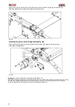
Fig.24
Thicknesser
If present, remove the bit from the mortising head and check that the planing blades are correctly
positioned and engaged.
Unlock the tables by turning the lever (Fig. 11.1) half a turn and pulling it backwards, thus tilting the tables.
This process will open the table.
Turn the protective cover over so that it covers the planer shaft and the feed rollers (Fig. 25).
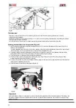
Setting the thickness to be planed (Fig. 25)
1. Set the planing thickness using the handwheel (Fig. 25.1) and lock the table with the lever (Fig. 25.2)
which is the handwheel.
If, after repeated use, this lever is in such a position that it cannot be tightened, loosen the cap nut, pull
the lever back, turn it one-sixth of a turn to the left and retighten the nut.
2. The table height should be adjusted so that there is a maximum gap of 1 mm between the top of the
workpiece and the connecting rod between the two ball bearing housings.
3. The thicknesser is equipped with a kickback protection.
4. The feed rollers can be engaged by pushing the lever (fig. 25.4) to the left. The drive wheel is then
pressed against the planer shaft by a spring.
5. In case of overload, stop the feed rollers and the planer motor as soon as possible. Reduce the material
intake before restarting the motor.
6. The thickness is read using the gauge (Fig 25.3).
Fig 25
Important
A smooth table surface is necessary to ensure the smooth operation of the thickness planer. Therefore, rub
the planer tables at regular intervals with a silicone or paraffin-based product. Use a stand to support long
pieces of wood.
.
4
1
2
3
Содержание RDJ 310-M
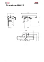
Страница 7: ...7 Dimensions RDJ 310 ...
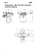
Страница 8: ...8 Dimensions RDJ 310 with mortising machine Option ...
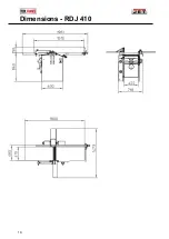
Страница 10: ...10 Dimensions RDJ 410 ...
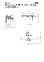
Страница 11: ...11 Dimensions RDJ 410 with mortising machine Option ...

