background image


10

8.0

  Adjustments 

8.1

  Table and blades 

1.  If the table requires adjustment, loosen four 

bolts (21); do not remove. Loosen nuts on the 
adjusting screws (18,19). The bed must rest 
squarely on the right and left hand side panels 
at all four corners while screws are loose. 
Shim legs at floor if necessary.  Tighten 
hardware. 

2.  Use set screw (18) and hex cap screw (19), to 

adjust the lower blade toward or away from the 
upper blade. The distance between the upper 
and lower blades should be 0.002-0.005”. 

Do 

not

 let the blades overlap.   

3.  Connect machine to electrical supply, and 

adjust the air pressure until the gauge reads 
approximately 90 psi. 

4. 

Place a heavy sheet of paper 
(~0.005”/0.13mm) in the cutting position, along 
the entire length of the bed.  

5.  Turn switch to ON and press the foot pedal. 

6.  If the shear does not cut the paper, move the 

lower blade toward the upper blade. 

7.  If the shear cuts the paper on the ends, but not 

the center, turn the tie-rod adjusting screw 
(37), clockwise until the paper is cut the entire 
length. 

8.  If the shear cuts the paper in the center, but 

not the ends, turn the tie-rod adjusting screw 
(37) counter-clockwise until the paper is cut 
the entire length. 

9.  Make sure the scales (15,16) on top of the 

table are square to the blade, and also show 
the correct distance from the blade.  

10. Make test cuts to verify that the scales are 

correct.  

8.2

  Air regulator 

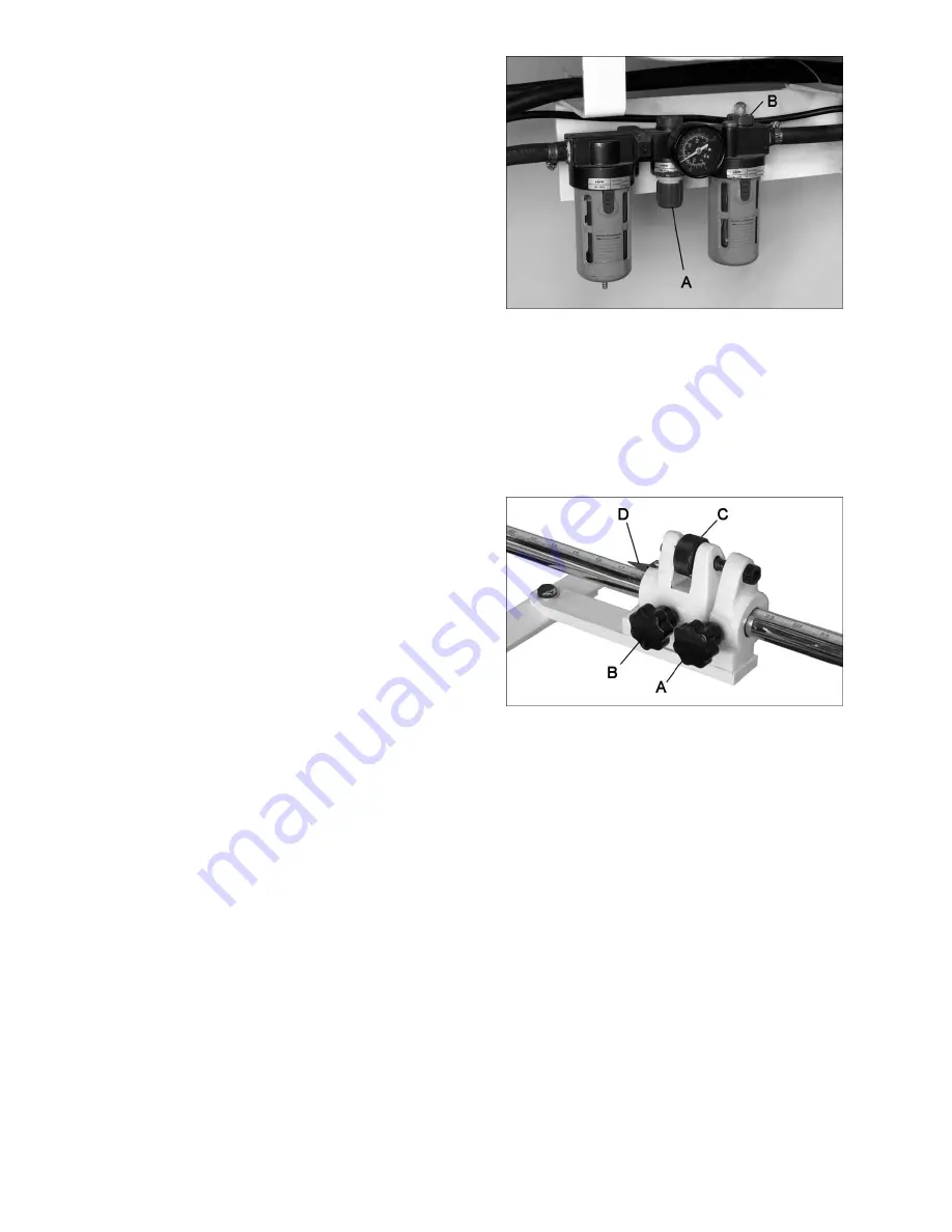
Refer to Figure 4. 

1.  Connect air source to quick connector. 

2.  Set the desired air pressure between 90-120 

PSI using the pressure dial (A) on the 
filter/regulator (clockwise to increase). Lock the 
setting by pushing down the pressure dial. Pull 
up on the dial to readjust a setting.  

3.  Adjust oil flow using dial (B) at top of 

lubricator

A setting of 2 drips per minute is sufficient for 
regular operation. 


Figure 4 

8.3

  Rear stop micro adjust 

Refer to Figure 5. 

The knurled dial on the adjusting block can be 
used for micro positioning of the rear stop. Tighten 
knob (A) and make knob (B) snug. Rotate dial (C) 
until pointer (D) is at desired position. Tighten knob 
(B). 


Figure 5 

8.4

  Hold-down tension 

The spring return can be adjusted on the hold 
down (3) by tightening the lower hex nuts (10). 

8.5  

Gibs 

There are three hex cap screws (32) that can be 
adjusted for play in each shim (31). Loosen the jam 
nuts (33) to turn the screws. Adjust for smooth 
travel. Retighten jam nuts. 


Содержание PS-1652T

Страница 1: ...nstructions and Parts Manual 16ga x 52 inch Pneumatic Shear Model PS 1652T JET 427 New Sanford Road LaVergne Tennessee 37086 Part No M 756203 Ph 800 274 6848 Revision C1 08 2018 www jettools com Copyr...

Страница 2: ...ne is in use If removed for maintenance purposes use extreme caution and replace the guards immediately after maintenance is complete 13 Check damaged parts Before further use of the machine a guard o...

Страница 3: ...your local supplier or JET JET can also be reached at our web site www jettools com Retain this manual for future reference If the machine transfers ownership the manual should accompany it WARNING So...

Страница 4: ...ional action needed JET has Authorized Service Centers located throughout the United States For the name of an Authorized Service Center in your area call 1 800 274 6846 or use the Service Center Loca...

Страница 5: ...d Assembly 8 7 1 Hole center dimensions 8 7 2 Unpacking 8 7 3 Stop assemblies 8 7 4 Electrical connections 9 8 0 Adjustments 10 8 1 Table and blades 10 8 2 Air regulator 10 8 3 Rear stop micro adjust...

Страница 6: ...on Adjusting Nuts 15 Left Scale 16 Right Scale 18 19 Table Adjustment Screws 21 Table Bolts 32 Gib Screws 37 Tie Rod Adjustment Screw 40 Screws for securing Scale Rods 59 Rear Stop 61 Adjusting Block...

Страница 7: ...e psi 85 100 0 6 0 7 Mpa Air consumption approx cfm 25 4 Air consumption per stroke approx cfm 1 4 Strokes per minute 40 without load 20 with load Recommended air hose diameter 1 2 Air hose inlet NPT...

Страница 8: ...Remove the bolts holding the machine to the skid 5 Place straps below the table you may have to remove front cover and use propery rated lifting equipment to move the machine to a level foundation Mac...

Страница 9: ...tool is properly grounded Repair or replace a damaged or worn cord immediately Use only 3 wire extension cords that have 3 prong grounding plugs and 3 pole receptacles that accept the machine s plug A...

Страница 10: ...ut not the ends turn the tie rod adjusting screw 37 counter clockwise until the paper is cut the entire length 9 Make sure the scales 15 16 on top of the table are square to the blade and also show th...

Страница 11: ...ts Blades dull Replace or sharpen blades Incorrect gap between blades Correct gap Loose gibs Remove backlash from gibs Cuts not square Inadequate hold down pressure Adjust pressure of hold down Blade...

Страница 12: ...12 11 1 1 PS 1652T Assembly Exploded View...

Страница 13: ...ower Knife 1 26 FS1636N 27 Cap Screw M10x45 9 27 PS1652T 27 Cap Screw M10x50 24 28 FS1636N 28 Washer 9 29 FS1636N 29 Washer 10mm 17 31 PS1652T 31 Gib 2 32 TS 1505071 Socket Head Cap Screw M10x45 6 33...

Страница 14: ...Washer 8mm 8 103 PS1652E 103 Magnetic Valve 4V310 10 AC110V 1 104 PS1652E 104 Muffler PT1 4 2 105 PS1652T 105 Pan Head Machine Screw M4x40 2 106 TS 1550021 Plain Washer 4mm 2 107 TS 2361041 Helical Sp...

Страница 15: ...652T 120 Foot Pedal Guard SFMS 1 1 142 5712561 Phillips Pan Head Machine Screw M5x8 4 143 PS1652T 143 Switch Box s n 11120022 and higher BX1 22 1 144 PS1652T 144 Select Switch s n 11120022 and higher...

Страница 16: ...16 12 0 Electrical connections 427 New Sanford Road LaVergne Tennessee 37086 Phone 800 274 6848 www jettools com N L PE N1 L1 XT JK YV L2 L1 N1 PE...

Отзывы: