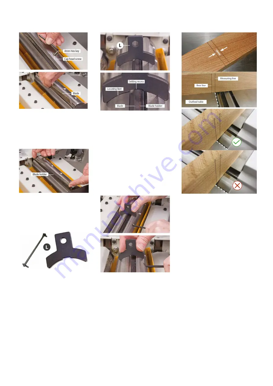
Fig 18
Remove the blade holder and lay aside.
Clean the slot housing thoroughly,
remove any resin build-up, sawdust,
chips etc. Clean the blade holder and
ensure the circumference of the cutter
block is cleaned thoroughly, see Fig 19.
Fig 19
Remove the new blade from its keeper
and place the old blade in it’s place.
Locate the
blade setting tool (L), see
Fig 20.
Fig 20
Introduce the blade holder, position it
against the back of the slot, introduce
the blade in the front of the blade
holder. Carefully position the blade and
the holder to line up with the edge of
the cutter block. Press the blade setting
tool gently down onto the blade,
ensuring the locating feet are firmly
seated against the circumference of the
cutter blockand the blade is against the
setting recess, see Fig 21.
Fig 21
Holding the blade and setting tool (L) in
position, tighten two cap head screws to
provide a firm clamp on the blade.
Keeping the setting tool held firmly in
place tighten the remaining cap head
screws, see Fig 22.
Repeat the procedure for the other two
blades. When allthe blades are set at
the correct height, carry out a quick
check by rotating the cutter block in
reverse and visually inspectingthe edge
of the blade against a fixed point.
Fig 22
If this appears satisfactory, go round
and check everything is tight and lower
the surface tables and re-lock them in
place. Replace the fence assembly and
continue with the operation.
NOTE: You can also check that the
blades are set at thecorrect height
along the length of the cutter block
bythe following method below.
Fig 23
• Find a scrap piece of timber and draw
two measuring lines approximately 3-
4mm apart, see Fig 23.
• Place the timber to one side of the
cutter block across the tables and line
up right measuring line to the edge of
the outfeed surface table, see Fig 23.
• Rotate the cutter block so the blade tip
pulls the timber forward, stop when the
blade detaches itself from the timber.
• The rear line should now line up with
the outfeed table’s edge, see Fig 23.
7.2 Setting the Machine for
Thicknessing
1. Remove the fence assembly and
place it in its holder to the rear of the
machine. Unlock the surface table and
raise them to the upright position.
2. Rotate the dust extraction hood until
it’s in the upright position.
3. Raise the locking lever to engage the
thicknessing function, see Fig 24.
Содержание JPT-F260-M
Страница 13: ...A1 A2 A3 A4 ...


