background image


13


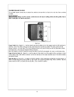
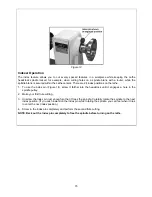
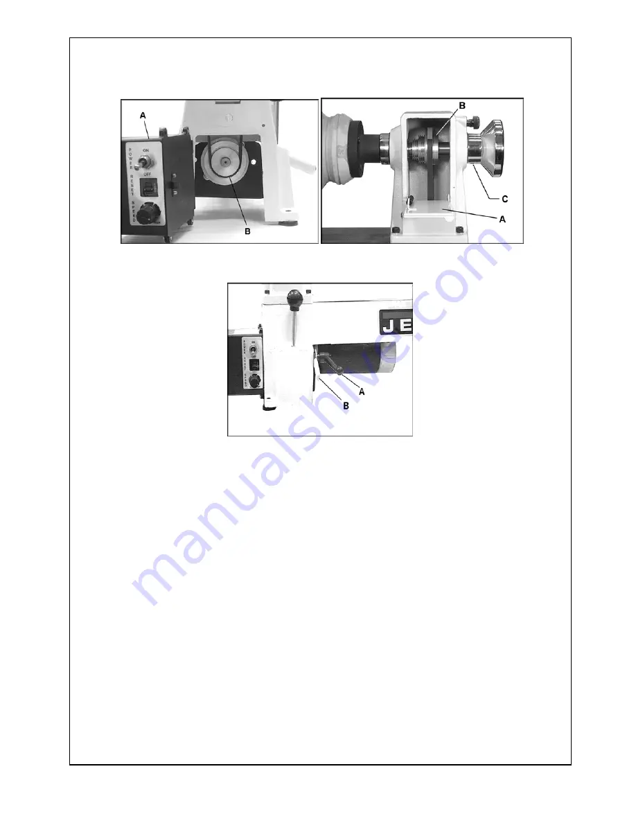
Figure 10                                                          Figure 11 


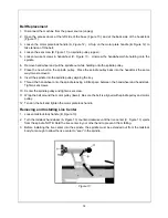
Figure 12 

Changing Spindle Speeds 

The variable speeds of the lathe are controlled by the speed knob on the control box as well as the 
position of the belt on the pulleys. 

1.  Disconnect machine from the power source (unplug). 

2.  Pull open the control box at the left side of the base (A, Figure 10), and the access door at the back 

side of the headstock (A, Figure 11)  to expose the pulleys. 

3.  Loosen the motor plate lock handle (A, Figure 12).  Lift up on the motor plate handle (B, Figure 12) to 

take tension off the belt. 

4.  Move the belt (B, Figure 10) to the desired pulley groove according to the speed chart found on the 

inside of the headstock access door.  Be sure the belt is aligned with spindle pulley and motor pulley. 

5.  Tension the belt by pushing down on the motor plate handle (B, Figure 12) and lock in place. 


Содержание JML-1014VSI

Страница 1: ...d Parts Manual Variable Speed Mini Lathe Model JML 1014VSI and JWL 1220VS WMH TOOL GROUP 2420 Vantage Drive Elgin Illinois 60124 Part No M 708375VS Ph 800 274 6848 Revision A2 1 08 www wmhtoolgroup com Copyright WMH Tool Group ...

Страница 2: ...postage prepaid to a location designated by us For the name of the location nearest you please call 1 800 274 6848 You must provide proof of initial purchase date and an explanation of the complaint must accompany the merchandise If our inspection discloses a defect we will repair or replace the product or refund the purchase price at our option We will return the repaired product or replacement a...

Страница 3: ... Keep guards in place and in working order Remove adjusting keys and wrenches Form the habit of checking to see that keys and adjusting wrenches are removed from the tool before turning it on Keep the work area clean Cluttered areas and benches invite accidents Do not use in a dangerous environment Don t use power tools in damp or wet locations or expose them to rain Keep work area well lighted Ke...

Страница 4: ... injury Never stand on a tool Serious injury could occur if the tool is tipped or if the cutting tool is unintentionally contacted Check damaged parts Before further use of the tool a guard or other part that is damaged should be carefully checked to determine that it will operate properly and perform its intended function Check for alignment of moving parts binding of moving parts breakage of par...

Страница 5: ...ariable Speed Range RPM 500 3 900 200 4300 Headstock Spindle Threads in x T P I 1 x 8 Hole Through Spindle in 3 8 Headstock Spindle Taper MT 2 Tailstock Spindle Taper MT 2 Hole Through Tailstock in 3 8 Tailstock Ram Travel in 2 Toolrest Length in 6 6 10 Motor 1 2 HP 1Ph 115V 3 4 HP 1PH 115V Overall Dimensions in L x W x H 28 1 8 x 10 1 4 x 14 1 8 41 x 12 x 15 1 2 Net Weight lbs approx 69 106 The a...

Страница 6: ...heck with a qualified electrician or service personnel if the grounding instructions are not completely understood or if in doubt as to whether the tool is properly grounded Use only three wire extension cords that have three prong grounding plugs and three pole receptacles that accept the tool s plug Repair or replace a damaged or worn cord immediately This tool is intended for use on a circuit t...

Страница 7: ... Use of heavy solvents paint thinner gasoline etc will damage painted surfaces Contents of the Shipping Carton JML 1014VSI 708375VS JWL 1220VS 708376VS 1 Lathe with motor and tailstock 1 Lathe with motor and tailstock 1 Control Box with 2 screws 1 Control Box with 2 screws 1 6 Tool rest 2 Tool rests 6 10 1 Face plate 1 Face plate 1 Knockout rod 1 Knockout rod 1 Live center 1 Live center 1 Spur cen...

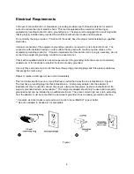
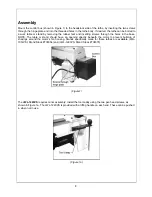
Страница 8: ...holes in the base NOTE The table or stand should have an opening directly beneath the motor to prevent build up of shavings around the motor s fan housing Stands specifically made for these lathes are available JML 1014VSI Stand Stock 708354 and JWL 1220VS Stand Stock 708378 Figure1 The JWL 1220VS requires minor assembly Install the tool caddy using the two pan head screws as shown in Figure 1a Th...

Страница 9: ...his can be useful for inserting a long bit to drill a hole in the center of a workpiece on the faceplate The clamping device on the tailstock has been factory adjusted however if further adjustment should be needed slide the tailstock off the end of the bed and tighten or loosen the nut D Figure 3 beneath the tailstock Work Lamp JWL 1220 only The 20 lathe is provided with a flexible work lamp whic...

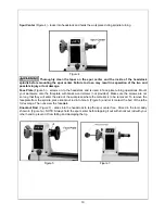
Страница 10: ...ce onto the faceplate with brass wood screws not provided Make sure the screws are not so long that they will enter the area of the workpiece where the material is to be removed To remove the faceplate from the spindle place knockout rod into hole A Figure 5 and let it contact the bed of the lathe for leverage Then unscrew the faceplate Knockout Rod Figure 7 slides into the headstock to tap the sp...

Страница 11: ...base on the bed by releasing the lock handle A Figure 8 and sliding onto the desired position Tighten handle A Figure 8 to lock Adjust the height of the tool rest by loosening handle B Figure 8 and raising or lowering tool rest Figure 8 Should adjustment of the tool rest clamping device become necessary turn off the machine reach under the bed and adjust the clamping nut Figure 3 NOTE The lock lev...

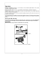
Страница 12: ...t will take the motor to reach the speed set by the speed control knob depends on the size and weight of the workpiece Move the switch to the OFF position to stop the lathe Wait for the workpiece to come to a complete stop Speed Control Knob B Figure 9 sets the speed of the lathe to suit the weight of the workpiece or type of tool being used After lathe is started turn knob clockwise to increase s...

Страница 13: ...re 10 and the access door at the back side of the headstock A Figure 11 to expose the pulleys 3 Loosen the motor plate lock handle A Figure 12 Lift up on the motor plate handle B Figure 12 to take tension off the belt 4 Move the belt B Figure 10 to the desired pulley groove according to the speed chart found on the inside of the headstock access door Be sure the belt is aligned with spindle pulley...

Страница 14: ...as removed 8 Insert the spindle into the spindle pulley aligning the key 9 Thread the handwheel onto the spindle leaving a little space between the handwheel and headstock Tighten set screws 10 Center the spindle pulley and tighten set screw 11 Wrap the belt around the motor pulley lower Be sure the belt is aligned with spindle pulley and motor pulley 12 Tension the belt and tighten the motor plat...

Страница 15: ...ndex pin Figure 14 screw it farther into the headstock until it engages a hole in the spindle pulley 2 Make your first flute cutting 3 Unscrew the index pin just enough so that it frees the spindle Carefully rotate the spindle to the next index position If you push inward on the index pin while rotating the spindle you can feel when it tries to enter the next index position 4 Screw in the index pi...

Страница 16: ...16 Parts Breakdown for JML 1014VSI Lathe ...

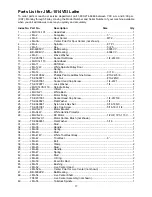
Страница 17: ...24NC 3 17 TS 0207061 Socket Head Cap Screw 1 4 20 1 4 18 TS 0720071 Lock Washer 1 4 4 19 JML1014VSI 119 Spindle Pulley 1 20 JML 20 V Belt 1 21 JMLVS 21 White Bed 1 22 JMLVS 22 Motor Pulley 1 23 TS 0207031 Socket Head Cap Screw 1 4 20 5 8 2 24 TS 0680021 Flat Washer 1 4 2 25 TS 0640081 Nylon Lock Hex Nut 5 16 18NC 1 26 TS 0051061 Hex Cap Screw 5 16 18 1 1 4 1 27 JMLVS 27 Motor Bracket 1 28 JML 34W ...

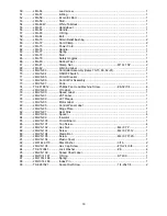
Страница 18: ...JMLVS 87 Knob 1 74 TS 081B012 Phillips Pan Head Machine Screw 8 32 1 4 4 75 JMLVS 89 I D Label 1 76 JMLVS 90 Speed Label 1 77 JMLVS 91 JET Label 1 78 JMLVS 92 JET Plaque 1 79 JMLVS 93 Motor Label 1 80 JMLVS 95 Control Panel Label 1 81 JMLVS 96 Hinge Plate 1 82 JMLVS 97 Heat Sink 1 83 JMLVS 98 Spacer 4 84 JMLVS 99 Insulator 1 85 JMLVS 100 Circuit Board 1 86 JMLVS 101 Tap Screw 4 87 JMLVS 102 Hex Nu...

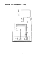
Страница 19: ...19 Electrical Connections JML 1014VSI ...

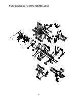
Страница 20: ... 12 14 7 10 13 42 41 43 44 81 55 60 57 56 9 61 62 64 44 81 86 45 37 87 88 89 78 68 83 72 54 53 52 52A 17 18 71 72 73 15 20 79 49 50 49 51 11 84 68 59 63 58 34 33 35 28 29 30 31 32 66 85 16 86 19 6 5 4 2 3 3A 21 76 77 38 39 40 46 47 48 47 75 74 67 82 71 101 102 ...

Страница 21: ...tor 1 25 JWL1220VS 125 Circuit Board 1 26 JMLVS 101 Tapping Screw 4 27 TS 1540021 Hex Nut M4 1 28 JML 28 Motor Pulley 1 29 TS 0050021 Hex Cap Screw 1 4 20x5 8 2 30 TS 0720071 Lock Washer 1 4 2 31 TS 0640081 Nylon Insert Lock Nut 5 16 18 1 32 TS 0051061 Hex Cap Screw 5 16 18x1 1 4 1 33 JWL1220 133 Motor Bracket 1 34 JWL1220 134 White Handle Protector 1 35 JWL1220VS 135 Motor 3 4HP 1Ph 115V 1 JWL122...

Страница 22: ... 174 Strain Relief SB6R 3 3 75 JWL1220VS 175 Power Cord 1 76 JWL1220VS 176 Cover Plate 1 77 TS 0810012 Pan Head Screw 10 24x1 4 2 78 JWL1220 198 Work Lamp 1 79 JML 79 Safety Goggles 1 80 JML 80 Rubber Foot 4 81 JML 81 Clamp Nut 2 82 JML 82 Warning Label 1 83 JWL1220 197 Cord Wrap Bracket 2 84 JWL1220 195 Tool Shelf 1 85 JWL1220 194 C Ring STW 10 4 86 TS 1523031 Socket Set Screw M6x10 3 87 JML1014 ...

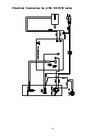
Страница 23: ...23 Electrical Connection for JWL 1220VS Lathe ...

Страница 24: ...24 WMH Tool Group 2420 Vantage Drive Elgin Illinois 60124 Phone 800 274 6848 www wmhtoolgroup com ...

Отзывы: