6. Machine operation
Warning:
Avoid kickback by sanding in
accordance with directional arrow.
Sand on downward side of disc only.
Sanding on the upward side could
cause the workpiece to fly up causing
injury!
Never sand with the sanding disc
guard not in place.
Failure to comply may cause serious
injury!
Feed the workpiece straight across the
machine table, holding your fingers
close together, guiding the workpiece
with the palm of your hands.
Don’t put your hands under the
machine table.
Always keep your hands well clear of
the moving sanding disc.
When working complex shapes, make
jigs and guides to guide the workpiece
properly and safely.
Support long workpieces with helping
roller stands.
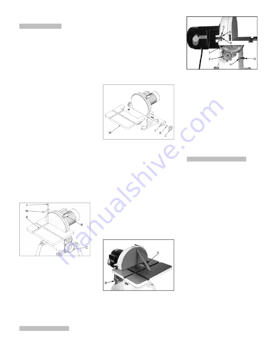
For bevel sanding the table can be
tilted.
The centre point
(A, Fig 6) provided
with the machine can be used for
circular sanding. Adjust the radius and
tighten the set screws.
Fig 6
The filler bar
(H, Fig 6) should be
added when sanding small
workpieces.
Secure in place with the socket head
cap screw (I). When not using the
filler bar thread the socket head cap
screw in the tapped hole as a stop.
7. Setup and adjustments
General note:
Setup and adjustment work may
only be carried out after the
machine is protected against
accidental starting by pulling the
mains plug.
7.1 Sanding disc replacement
Disconnect the machine from the
power source (pull mains plug).
Remove the sanding disc guard (O,
Fig 4).
Fig 7
Remove the knobs (J, Fig 7) washers
(K), trunnion holders (L) and the
machine table (M).
Remove the old sanding disc.
Make sure the disc plate is clean
before you attach the new sanding
disc .
Reattach the machine table and the
sanding disc guard .
7.2 Table adjustment
Disconnect the machine from the
power source (pull mains plug).
Use a square (A, Fig 8) on the sanding
disc to exactly align the table to 90°.
Fig 8
Set the 90° stop screw (C, Fig 8) and
lock the nut (D).
Set the pointer so that it reads 0°.
Fig 9
If adjustment of 45°stop is needed,
loosen the hex nut (H, Fig 9 ) and
adjust the socket head cap screw (G).
Always maintain a gap of
approximately 2mm between the table
edge, and disc.
If adjustment is necessary loosen hex
cap bolts (I).
Move the mitre gauge and inspect the
parallelism of the movement in
regards to the sanding disc.
If the mitre guidance is not parallel
loosen the hex cap bolts (I) and adjust.
8. Maintenance and inspection
General note:
Maintenance, cleaning and repair
work may only be carried out after
the machine is protected against
accidental starting by pulling the
mains plug.
Check sanding disc regularly for faults.
Replace a defective sanding disc
immediately.
Clean the machine regularly.
Inspect the proper function of the dust
extraction daily.
Defective safety devices must be
replaces immediately.
Repair and maintenance work on the
electrical system may only be carried
out by a qualified electrician.
Cleaning of Canister filter (Option)
Disconnect the machine from the
power source.
Take off the grounding clip and
remove the filter by turning clockwise.
Empty the contents into an appropriate
container.
The filter can be cleaned with a low
pressure air hose. Blow from the
outside of the filter to clean the dust
particles.


