background image

 14 

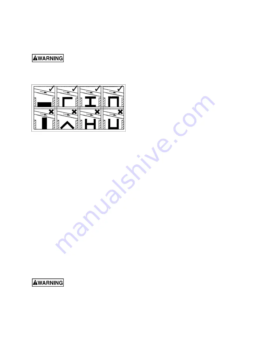
The top row shows acceptable clamping 
positions, the bottom row shows 

un

acceptable 

positions. 

If the thickness of profile section is very thin, a 
piece which duplicates the profile should be 
fitted inside the workpiece itself, to prevent 
workpiece being crushed between the jaws. 


Do not load/unload material 

from vise while machine is running. Never hold 
workpiece by hand when cutting; workpiece 
must be firmly secured in vise. Do not reach into 
cutting area during cutting operations.


Figure 23:  clamping positions 

3.  Adjust blade guides to minimize exposed blade 

area. 

4.  Release support and turn on saw. Lower bow 

until blade contacts material. Release bow to 
allow cutting to proceed. Weight of bow in 
conjunction with spring tension will force blade 
through material until cut is finished. 

5.  Switch trip tab must turn off saw at completion 

of cut.  

8.3

  Evaluating cutting efficiency 

Is the blade cutting efficiently? The best way to 
determine this is to observe the chips formed by the 
cutting. 

If chip formation is powdery, then the feed rate is 
much too light, or the blade is dull. 

If chips are curled, but colored — that is, either blue 
or straw-colored from heat generated during the cut 
— then the feed rate is too high. 

If chips are slightly curled and are not colored by 
heat, the blade is sufficiently sharp and is cutting at 
its most efficient rate. 

9.0

  User-maintenance 

 Always disconnect power to 

the machine before performing maintenance.   
Failure to do this may result in serious personal 
injury. 

Wipe down saw with a soft rag after each use, and 
clear metal particles with a small paint brush or parts 
cleaning brush. Do not use compressed air, as it 

may force chips into the guide bearings and other 
critical areas of saw.   

Periodically apply a light coat of oil on exposed 
metal surfaces to inhibit rust. 

Make frequent inspections of motor fan, and blow 
out (with low pressure air hose) or vacuum any 
accumulation of foreign material to maintain normal 
motor ventilation.  

Keep blade guides clean and free of metal particles.  

Check guide bearings frequently to make sure that 
they are properly adjusted and turning freely. 

Periodically inspect belt for wear or fraying. Replace 
if needed. 

Inspect power cord; if worn, cut or damaged in any 
way, have it replaced immediately. 

9.1

  Lubrication 

Ball bearings on blade guide assemblies and blade 
wheels are permanently lubricated and sealed, and 
should require no further lubrication. 

Lubricate the vise lead screw as needed with #2 
tube grease. 

Drain and refill gear box oil after first 90 days of 
operation. Thereafter, change every six months. 
Use MOBIL SHC 634 or equivalent.  

To change gear box oil: 

1.  Disconnect machine from power source. 

2.  Place bow in horizontal position. Loosen or 

remove screw and nut on motor tension plate 
(see A, Figure 12). Remove drive belt and allow 
motor to drop away, for access to gearbox. 

3.  Remove four screws from gear box (Figure 24) 

and remove cover plate and gasket. 

4.  Hold a container under lower right corner of 

gear box with one hand while slowly raising bow 
with the other. Drain completely. 

5.  Place arm in horizontal position. Wipe out 

remaining oil with a rag. 

6.  Fill gear box with approximately 1/2 pint of 

MOBIL SHC 634. 

7.  Replace gasket and cover. Fasten cover with 

screws. 

8.  Reinstall and tension drive belt, and secure nut 

on tension plate (A, Figure 12). 

Содержание HVBS-56

Страница 1: ...Parts Manual Horizontal Vertical Band Saw Model HVBS 56 JET 427 New Sanford Road LaVergne Tennessee 37086 Part No M 414458 Ph 800 274 6848 Revision H5 06 2020 www jettools com Copyright 2017 JET This...

Страница 2: ...djusting keys and wrenches Form a habit of checking to see that keys and adjusting wrenches are removed from the machine before turning it on 12 Keep safety guards in place at all times when the machi...

Страница 3: ...Saw This manual contains instructions on installation safety precautions general operating procedures maintenance instructions and parts breakdown Your machine has been designed and constructed to pro...

Страница 4: ...11 7 6 Blade guide bearings 11 7 7 Blade tracking 12 7 8 Feed pressure adjustment 12 7 9 Blade to table squareness 12 7 10 Auto shut off adjustment 13 7 11 Vise adjustment 13 7 12 Vertical stop adjust...

Страница 5: ...120 200 SFPM Blade wheel diameter 7 3 8 in 187 mm Bed and vise Bed height from floor 25 1 2 in 648 mm Vise swivel 45 deg Main materials Bed cast iron ground surface Bow cast iron Stand steel Blade dr...

Страница 6: ...ews 5 16x1 1 4 HP2 2 Cotter pins 1 8x1 HP3 6 Flat washers 5 8 HP4 20 Flat washers 1 4 HP5 21 Hex nuts 1 4 HP6 1 Flat head screw 1 4 x 3 4 HP7 6 Flat washers 5 16 HP8 2 Hex cap screw 3 16x1 2 HP9 6 Hex...

Страница 7: ...cure 4 Install adjustable feet C at opposite end of stand and adjust until stand is level 5 5 Mounting saw to stand Saw is heavy two person lift 1 With help from another person position saw atop stand...

Страница 8: ...115 volt The band saw comes with a plug designed for use on a circuit with a grounded outlet that looks like the one pictured in A Figure 8 Before connecting to power source be sure switch is in off p...

Страница 9: ...rated in D Make sure the tool is connected to an outlet having the same configuration as the plug No adapter is available or should be used with this tool If the tool must be reconnected for use on a...

Страница 10: ...while tightening hex nut A until finger pressure on the belt between the two pulleys causes approximately 1 2 inch deflection Do not overtighten belt 6 Close pulley cover and connect to power source...

Страница 11: ...blade Figure 15 6 Place new blade between blade guide assemblies and around each wheel Make sure blade teeth are pointing in proper direction Figure 16 Tension enough to hold in place Figure 16 7 Inst...

Страница 12: ...itive start with 1 4 turns on the set screw and allow blade to respond to changes 9 Once tracking is set tighten bolts M Figure 18 7 8 Feed pressure adjustment Turn handle O Figure 19 clockwise to dec...

Страница 13: ...which is easily damaged if a careful break in procedure is not followed Consult the blade manufacturer s literature for break in of specific blades on specific materials However the following procedu...

Страница 14: ...articles with a small paint brush or parts cleaning brush Do not use compressed air as it may force chips into the guide bearings and other critical areas of saw Periodically apply a light coat of oil...

Страница 15: ...d wires Short circuit in motor or loose connections Inspect all connections on motor for loose or shorted terminals or worn insulation Incorrect fuses or circuit breakers in power line Install correct...

Страница 16: ...for material Use proper blade Rough cut Improper blade break in Follow proper break in procedure Improper speed or feed rate Adjust as needed Dull or damaged teeth Replace blade Poor weld on blade Rep...

Страница 17: ...17 11 1 1 HVBS 56 Bow Assembly Exploded View...

Страница 18: ...18 11 1 2 HVBS 56 Bed Assembly Exploded View...

Страница 19: ...1 35 TS 0680041 Flat Washer 3 8 x1 2 36 TS 0090061 Hex Cap Bolt 3 8 x1 1 4 1 37 HVBS462 037G Bed 1 38 HVBS462 038 Cross Round Head Screw 3 16 x3 8 2 39 HVBS462 039 Scale 1 40 HVBS462 040 Electric Cord...

Страница 20: ...BS462 085 02 Capacitor not shown 1 86 HVBS462 086 Motor Pulley 1 87 BB 6202ZZ Ball Bearing 6202ZZ 6 88 HVBS462 088 Bearing Bushing 1 89 OS 15375 Oil Seal 2 90 HVBS462 090 Transmission Wheel Shaft 1 91...

Страница 21: ...56 HVBS462 156 Round Head Screw 3 16 x3 4 1 157 HVBS462 157 Star Washer 3 16 3 158 HVBS463 158 Hex Nut 3 16 2 159 HVBS463 159 Round Cross Head Screw 3 16 x1 2 1 160 JET 92 JET Logo with 3M adhesive 92...

Страница 22: ...s Head Screw w lock washer 1 4 x 5 8 19 3 TS 0680021 Flat Washer 1 4 19 4 TS 0570011 Hex Nut 1 4 20 19 5 HVBS462 014 Floor Stand Handle 1 6 HVBS56M 09 Wheel 2 7 TS 0680081 Flat Washer 5 8 6 8 HVBS462...

Страница 23: ...23 12 0 Electrical Connections HVBS 56 Band Saw...

Страница 24: ...tional action needed JET has Authorized Service Centers located throughout the United States For the name of an Authorized Service Center in your area call 1 800 274 6846 or use the Service Center Loc...

Отзывы: