background image

Содержание HBS-1018W

Страница 1: ...ENT TOOLS OPERATOR S MANUAL HBS 916W 1018W Bandsaws j p JET EQUIPMENT TOOLS INC A WMH Company www jettools com P O BOX 1349 Auburn WA 98071 1349 e mail jet jettools com 253 351 6000 Fax 253 939 8001 M 414468 2 99 ...

Страница 2: ...of maintenance JET LIMITS ALL IMPLIED WARRANTIES TO THE PERIOD SPECIFIED ABOVE FROM THE DATE THE PRODUCT WAS PURCHASED AT RETAIL EXCEPT AS STATED HEREIN ANY IMPLIED WARRANTIES OR MECHANTABILITY AND FITNESS ARE EXCLUDED SOME STATES DO NOT ALLOW LIMITATIONS ON HOW LONG THE IMPLIED WARRANTY LASTS SO THE ABOVE LIMITATION MAY NOT APPLY TO YOU JET SHALL IN NO EVENT BE LIABLE FOR DEATH INJURIES TO PERSON...

Страница 3: ...st blades or other moving parts Make all machine adjustments or maintenance with the machine unplugged from the power source Use the right tool Don t force a tool or attachment to do a job which it was not designed for Replace warning labels if they become obscured or removed Make certain the motor switch is in the OFF position before connecting the machine to the power supply Give your work undiv...

Страница 4: ...embly 1 2 ElectricalConnections 0 0 0 0 3 Controls 0 0 00 0 0 0 0 0 3 Prior To Operation 4 Adjusting Vise Square to Blade 5 Changing Blade Speeds 0 5 Adjusting Feed Rate 0 6 Changing Blades 6 Blade Tracking Adjustment 0 7 Automatic Shut Off Adjustment 0 0 0 0 8 Thrust Roller Adjustment 0 8 Guide Roller Adjustment 00 9 Bow Weight Adjustment 0 0 0 0 0 9 ViseAdjustment 0 00 0 0 0 0 0 0 0 0 0 10 Maint...

Страница 5: ... 1OW oil Installation For best performance the bandsaw should be located on a solid and level foundation Allow room for servicing and for moving large stock around the bandsaw when deciding a location for the machine 1 Using lifting straps that are isolated from the bandsaw s finished surfaces lift machine place in desired location See figure 1 for strap placement 2 Install four leveling bolts wit...

Страница 6: ...ig 3 from the right side of the saw arm 9 Slide belt cover 8 Fig 3 around pulley shafts and attach to saw with two hex cap bolts and two washers 10 Lift motor and place v belt around both pulleys Lower motor 11 Tension the v belt by pushing down on the motor and tightening the lock handle on the motor tilt plate Correct tension is achieved when finger pressure between the two pulleys causes approx...

Страница 7: ...o be changed Main Motor follow diagram insidejunction box cover Coolant Pump Remove chip pan on front of saw remove junction box cover on pump and follow diagram inside junction box cover Control Transformer Open electrical panel on rear of base and switch primary wire on transformer from 115V to 230V Machine must always be correctly grounded Note The power cord end will have to be changed to one ...

Страница 8: ...ight clearance between back up rollers and back of blade 5 Position blade guides as close to work piece as possible 6 Select proper speed and feed rate for material being cut See speed selection chart found in the enclosed Guide to Bandsawing booklet supplied with this saw 7 Material to be cut must be securely held in vise 8 Check to see that coolant level is adequate and turn on coolant pump if m...

Страница 9: ...nt Failure to comply may cause serious injury 1 Disconnect machine from the power source 2 Open pulley cover by supporting the belt cover with one hand while removing the belt cover lock knob with the other Lower guard gently to its full open position 3 Support motor with one hand while loosening lock handle A Fig 6 Lower motor gently 4 Position belt in grooves according to the speed selection cha...

Страница 10: ...Guide to Band Sawing published by American Saw and Manufacturing Company Reprinted by permission Changing Blades it WARNING Disconnect machine from the power source before making any adjustments or repairs Failure tQ comply l1 1ayresult in serious injury 1 Disconnect machine from power source 2 Raise saw arm approximately 6 Hold saw arm in place by closing cutting pressure control valve Remove scr...

Страница 11: ...mes into contact with blade teeth 11 Close all covers and guards and fasten securely Connect machine to power and run freely for approximately two minutes 12 Turn power off and re check blade tension and wire brush adjustment If further adjustment is necessary disconnect saw from power source make adjustments and re connectto power Blade Tracking Adjustment Blade tracking has been set at the facto...

Страница 12: ...acking is completed 8 Connect machine to the power source Automatic Shut Off Adjustment The motor should shut off immediatelyafter the blade has cut through the materialand just before the head comes to rest on the horizontalstop bolt If the machine continues to run after the work piece has been fully cut locate and adjust the micro switch mounting plate down If the machine shuts off before the wo...

Страница 13: ...e A 5 Fig 10 Tighten locking screws C 6 Slide blade guides back into contact with blade and tighten screws B 7 Connect machine to the power source Bow Weight Adjustment Bow weight is one of the most important adjustments of the saw If the bow weight is not set properly one can expect poor performance crooked cuts tooth stripping stalling and the blade popping off the bladewheels The hydraulic feed...

Страница 14: ...ock B Fig 11 to desired location by sliding along the bed Place the rack block onto the rack 3 Turn the handwheel to tighten the vise To adjust the vise for angle cutting 1 Loosen bolts and move vise jaw C Fig11 to desired location 2 Set the vise to desired angle reinstall nuts and Tighten the nut and bolt assemblies 3 Adjust the movable vise parallel to the fixed vise by loosening bolt D Fig 11 a...

Страница 15: ...nd on lower front of gear case under right wheel cover Remove drain plug with a hex wrench 3 Replace drain plug 4 Remove filler cap A Fig 12 and fill gear box with Mobil DTE Oil Heavy Medium until level reaches dot in middle of sight glass 5 Replace filler cap 6 Connect machine to the power source Use a light machine oil to lubricate all other moving parts as needed A detailed explanation on blade...

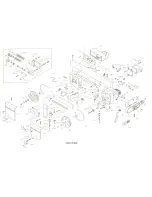
Страница 16: ... c E Q en en C Q Q C C ns Q I ns Q t 73 69 Ii 0 I 2 12161 N 203 1 201 _ 202 W JiJJ ...

Страница 17: ...175111 J IJ T 6 8 c E CD 1 1 1 1 E nI tn 122 111 121 3 i 9O 111 f ...

Страница 18: ...171 172 _ 112 41 113141 111 12 114 107 1 1084010914 110 O9 1 4 114 0 I 122 99 117 6 96 1 80 HBS 916W ...

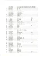
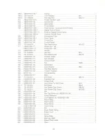
Страница 19: ... 1 12 TS 1490051 Hex Cap BoiL M8x30 8 13 TS 1550061 Washer M8 8 14 TS 1551081 LockWasher M8 8 15 TS 1540061 Hex Nut M8 8 16 HBS916W 16 Stop Bracket 1 17 HBS916W 17 Stop Rod 1 18 HBS916W 18 Lock Handle 1 19 HBS916W 19 Work Stop 1 20 HBS916W 20 Lock Knob 1 21 HBS916W 21 Hand Wheel Assembly 1 HBS1018W 21 Hand Wheel Assembly 1 22 HBS916W 22 Lead Screw Seat 1 HBS1018W 22 Lead Screw Seat 1 23 TS 1490051...

Страница 20: ... 1 52 HBS916W 52 Cylinder Pin 1 52 1 HBS916W 52 1 Pin 1 53 HBS916W 53 Hydraulic Mounting Plate Top 1 HBS1018W 53 Hydraulic Mounting Plate Top 1 53 1 TS 1551071 LockWasher M10 2 53 2 TS 1491041 Hex Cap Bolt M1Ox30 2 54 TS 1492051 Hex Cap Bolt M12x50 2 55 TS 1550081 Washer M12 2 56 HBS916W 56 Plate 1 57 TS 0561051 Hex Nut 1 2 2 58 HBS916W 58 Spring Bracket 1 59 HBS916W 59 Adjustable C Bolt 1 60 HBS9...

Страница 21: ...over righL 1 81 TS 1550041 Washer M6 4 82 HBS916W 82 Bushing 1 83 HBS916W 83 Washer 1 84 HBS916W 84 Drive Wheel 1 HBS1 018W 84A Drive Wheel 14 1 85 Blade local purchase 916W 1 Blade local purchase 1016W 1 86 HBS916W 86 Hose 1 87 TS 1533031 Pan Head Screw M5x10 2 88 HBS916W 88 Filter Screen 1 89 TS 1492031 Hex Cap BoiL M12x35 4 89 1 TS 1551 081 Lock Washer M12 4 90 HBS916W 90 Lock Knob 4 91 HBS916W...

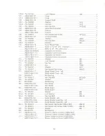
Страница 22: ...3 TS 1540061 Hex Nut M8 4 114 HBS916W 114 Key 7MM 1 115 TS 1550081 Washer M12 1 116 TS 1504041 Hex Socket Cap Screw M8x20 1 117 HBS916W 117 BladeWheel Cover left 1 HBS1018W 117A BladeWheel Cover left 1 118 BB 608W Ball Bearing 2 119 TS 1492011 Hex Cap BoiL M12x25 2 120 TS 1550081 Washer M12 1 121 BB 6205Z Ball Bearing 3 122 HBS916W 122 Idler Wheel 1 HBS1018W 122A IdlerWheel 1 123 HBS916W 123 Blade...

Страница 23: ...551061 LockWasher HBS 916W M8 2 141 HBS916W 141 Knob 1 HBS1018W 141 Knob 1 142 HBS916W 142 Plate 1 143 TS 1524021 Set Screw M8x10 4 144 HBS916W 144 Blade Bracket right 1 HBS1018W 144 Blade Bracket right 1 145 TS 1482011 Hex Cap Bolt M6x10 1 146 TS 1550041 Washer M6 1 147 HBS916W 147 Wire Brush 1 HBS1018W 147 Wire Brush 1 148 HBS916W 148 Wire Brush Rod 1 HBS1018W 148 Wire Brush Rod 1 149 HBS916W 14...

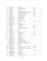
Страница 24: ...916W 178 Tension Shaft 1 179 HBS916W 179 Key 5MM 1 180 HBS916W 180 Handwheel 1 181 HBS916W 181 LockWasher M22 13 182 HBS916W 182 Flat SteelWasher 1 183 HBS916W 183 Tension Indicator 1 184 BB 51104 Thrust Bearing 1 187 HBS916W 187 Slide 1 188 TS 1524021 Set Screw M8x10 1 189 HBS916W 189 Extension Bar 1 190 HBS916W 190 Wheel Shaft 1 191 HBS916W 191 Nut w Hole For Set Screw M14 1 191 1 TS 1523021 Set...

Страница 25: ...BS916W 215 Cu Connector 1 HBS1018W 215 Cu Connector 2 216 TS 1504051 Hex SocketCap Screw M8x25 2 217 HBS916W 217 SlideBracket 1 218 HBS916W 218 LeadScrewBracket 1 219 HBS916W 219 RackBlock 1 HBS1018W 219 RackBlock 1 220 HBS916W 220 Rack 1 HBS1018W 220 Rack 1 221 HBS916W 221 Pin 1 21 ...

Страница 26: ... w G CD Q I C t I CD CD a c CD a t 0 s fa m 0 t tn tn CD 3 C 0 0 u jf c oc ...

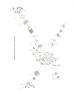
Страница 27: ...08 OUTPUT SHAFT COVER 1 9 HBS916W 94 09 OUTPUT HEX CAP SCREW M10x20 4 10 HBS916W 94 10 INPUT HEX CAP SCREW M8x20 4 11 HBS916W 94 11 INPUT SHAFT COVER 1 12 HBS916W 94 12 WASHER 1 13 HBS916W 94 13 BEARING 6025 1 14 HBS916W 94 14 INPUT SHAFT 1 15 HBS916W 94 15 KEY 7x7x60 1 16 HBS916W 94 16 BEARING 6205 1 17 HBS 16W 94 17 C RING R52 1 18 HBS916W 94 18 OIL SEAL 25x52x8 1 19 HBS916W 94 19 VENT BOLT 1 20...

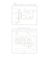
Страница 28: ...atic for the HBS 916W R STOP Selec Sw Pump AC 110 220V 5 0 4 0 L 6 s 220V Electrical Panel Layout 0 4 1 T U v W U v W a 1 2 3 4 51 0 t R S 0 115V 115V 230V 6 R 230 0 115 i m R S 2 TR 11OV 220V 0 0 0 0 6 S U2V2 5 U V 4 0 24 ...

Страница 29: ...trical Schematic for the HBS 1 a 18W R 220V 2 110V STOP AC 1 Selec Sw Pump 0 4 a L 6 s 220V Electrical Panel Layout 0 Lt iT U V w U v W 0 1 2 3 4 51 0 tt R S 0 115V 230V R 230 0 115 0 0 0 0 6 s u v 5 U V 4 0 25 ...

Страница 30: ......

Страница 31: ......

Страница 32: ......

Отзывы: