


5
Uncrating and Clean-Up
1. Remove the crate from around the machine.
2. Carefully clean all rust protected surfaces
with a mild solvent or kerosene and a soft
rag. Do not use lacquer thinner, paint
thinner, or gasoline. These will damage
painted surfaces.
3. Coat all machined surfaces with a light coat
of oil to inhibit rust.
4. Remove the bolts holding the machine to the
skid.
5. Carefully move the machine to a well lighted
area on a solid, level work bench, and
secure to the bench with lag screws or bolts.
6. Machine location must allow access to all
sides.
Brake Setup
The brake will not bend properly if it is not level.
Use a machinist’s level and shims if necessary.
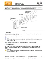
Apron Adjustments
The (#) in the text refers to the breakdown.
The apron assembly has been adjusted at the
factory for proper use of capacity material.
During shipment of this unit the machine may
have come out of alignment.
Forward edge
– The forward edge of the top
blade (1) should be adjusted parallel to the pivot
edge of the clamp block. Release clamping
pressure on the holddown assembly by pushing
clamp handles (8,9) slightly to the rear. Turn the
hex cap screws (16) to adjust for parallel.
Center
– The center of the apron can be adjust-
ed by tightening the truss nut on the apron
assembly (801).
Operating the Brake
Adjusting for Metal Thickness
The holddown assembly must be adjusted to
allow for clearance when making bends
according to the thickness of the material.
Clearance for material within four gauges of the
capacity should be twice the thickness of the
material. For lighter gauges use 1-1/2” times the
thickness. The forward edge of the top blade (1)
should be adjusted parallel to the pivot edge of
the clamp block. Release clamping pressure on
the holddown assembly by pushing clamp
handles (8,9) slightly to the rear. Turn the hex
cap screws (16) to adjust for parallel and proper
clearance. The center of the holddown can be
adjusted by tightening the truss nut on the
holddown assembly.
Adjusting the Clamping Pressure
The clamping pressure should be adjusted
according to the thickness of the material. The
clamping pressure should be great enough to
hold the material securely in place but not so
much that it is difficult to lock the clamping
handles. Clamping pressure can be adjusted by
turning the nuts (24) on the threaded rod portion
of the yoke assembly (8,9).
Flange Capacity
The recommended minimum flange in capacity
material is one inch.
Repeat Bends
Adjust the gauge stop (26) on the gauge rod
(31) to limit the swing of the apron assembly.
Counter Weight
The counter weight (44) can be moved up or
down to provide more or less leverage
depending on the material.
Lubrication
The machine must be lubricated every day of
service with a few drops of oil. Oil pinholes are
located at both yoke assemblies (8,9), and the
apron assembly near the hinge pin (23).
Lightly oil the machined parts when not in use to
prevent rust
Содержание HB-1697H
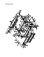
Страница 7: ...7 Assembly Drawing...