


14
9.0
Maintenance/Lubrication
Lathe must be serviced at all
lubrication points and all reservoirs filled to
operating level before the lathe is put into
service. Failure to comply may cause serious
damage to the lathe.
The ZH series lathe is shipped with oil in the
reservoirs. Coolant is not included.
Use clean lubricants and check levels often,
including before each working shift. To ensure
proper lubrication, oil levels should not be less than
the center of the oil sight glass. Try not to overfill,
as this may cause leakage.
A chart is supplied in
section 15.0
for quick
reference to all lubrication points.
Unless specified otherwise, the lubrication points
require a non-detergent, ISO 68, SAE 20W oil. The
recommended brand for this lathe is Mobil DTE
®
Oil Heavy Medium.
1.
Headstock
– Oil must be up to indicator mark
in oil sight glass at the
rear
of the headstock.
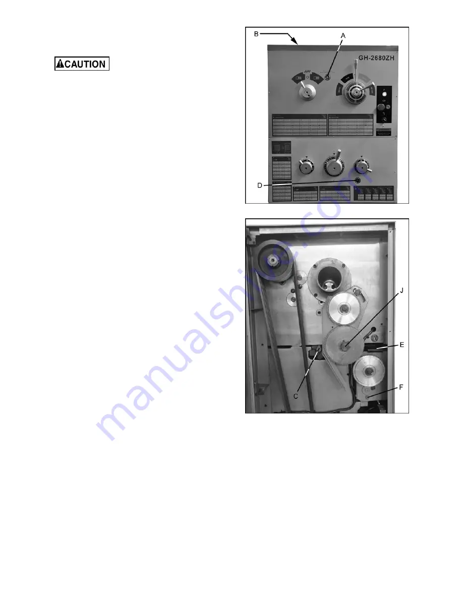
[NOTE: The sight glass on the
front
of the
headstock (A, Figure 8) verifies operation of
the oil pump, the one at
rear
of headstock (not
shown) indicates oil level]. Top off with SAE
20W oil. Fill by removing the rubber mat and
unscrewing the plug (B) on top of the
headstock.
2. To drain the headstock, remove the nut on the
drain pipe (C, figure 9). Drain oil completely
and clean out all metal shavings, then rinse
the casting case with kerosene. During the
breaking-in process for the lathe, the first oil
change should be after 10 days; the second
after 20 days. Then change the oil in the
headstock every three months.
Figure 8 – Headstock lubrication
Figure 9 – Lubrication points
3.
Oil Filter
– The filter should be cleaned once a
month. To access, open the top cover on the
headstock, unscrew the nut on the oil line, and
pull up the oil line to bring the filter up. See
Figure 10. Use a brush to clean.
Содержание GH-26120ZH
Страница 34: ...34 18 0 Change Gear Diagram Figure 54 ...
Страница 35: ...35 This page intentionally left blank ...
Страница 40: ...4 1 1 Bed Assembly I Exploded View ...
Страница 41: ...5 1 2 Bed Assembly I for 120 ZH only Exploded View ...
Страница 44: ...8 2 1 Bed Assembly II Exploded View ...
Страница 45: ...9 2 2 Bed Assembly II for 120 ZH only Exploded View ...
Страница 48: ...12 3 1 Headstock Assembly I Exploded View Ⅲ Ⅳ Ⅴ Ⅶ Ⅵ Ⅱ Ⅰ Ⅱb Ⅶb ZⅡ ZⅠ ZⅡ ...
Страница 51: ...15 4 1 Headstock Assembly II Exploded View ...
Страница 54: ...18 5 1 Headstock Assembly III Exploded View ...
Страница 56: ...20 6 1 Headstock Assembly IV Exploded View Ⅰ Ⅱb Ⅱ Ⅲ Ⅳ Ⅴ ...
Страница 59: ...23 7 1 Headstock Assembly V Exploded View Ⅶ Ⅶb Ⅵ ...
Страница 62: ...26 9 1 Gear Box Assembly I Exploded View Ⅱ Ⅲ Ⅰ ...
Страница 64: ...28 10 1 Gear Box Assembly II Exploded View ...
Страница 67: ...31 11 1 Gear Box Assembly III Exploded View ...
Страница 70: ...34 12 1 Brake Assembly Exploded View ...
Страница 72: ...36 13 1 Saddle and Cross Slide Assembly Exploded View ...
Страница 75: ...39 14 1 Tool Post and Compound Rest Assembly Exploded View ...
Страница 77: ...41 15 1 Apron Assembly I Exploded View Ⅱ Ⅹ Ⅱ Ⅲ Ⅷ Ⅹ Ⅸ Ⅹ Ⅳ Ⅰ Ⅹ Ⅰ Ⅵ Ⅲ Ⅴ Ⅶ ...
Страница 80: ...44 16 1 Apron Assembly II Exploded View Ⅺ Ⅹ Ⅲ Ⅻ Ⅸ Ⅹ Ⅶ ...
Страница 83: ...47 17 1 Apron Assembly III Exploded View Ⅰ Ⅱ Ⅴ Ⅲ Ⅳ Ⅵ ...
Страница 85: ...49 18 1 Apron Assembly IV Exploded View ...
Страница 87: ...51 19 1 Tailstock Assembly I Exploded View ...
Страница 89: ...53 20 1 Tailstock Assembly II Exploded View ...
Страница 91: ...55 21 1 Steady Rest Assembly Small and Large Exploded View ...
Страница 95: ...59 24 1 Travel Stop Assembly Exploded View ...
Страница 99: ...63 27 1 Electrical Components FR2 FR3 KM1 KM2 KM3 QF1 QF4 7 4 5 KA1 TC 2 3 11 10 1 QS 6 HL SB1 SB4 SA1 8 9 ...
Страница 100: ...64 27 2 Electrical Diagram ...


