4
Read the entire contents of
this manual before assembling or operating the
taper attachment. Also, thoroughly familiarize
yourself with all operation, maintenance and
safety instructions that accompany the lathe to
which the taper attachment will be mounted.
Failure to comply may cause serious injury.
Assembly
Numbers in parentheses (#) correspond to Figures
and to index numbers in exploded view.
1. Carefully remove taper attachment from box.
Do not discard any packing material until taper
attachment is assembled and operating
properly. If any damage or missing parts are
identified, contact your distributor immediately.
2. Remove splash guard from lathe.
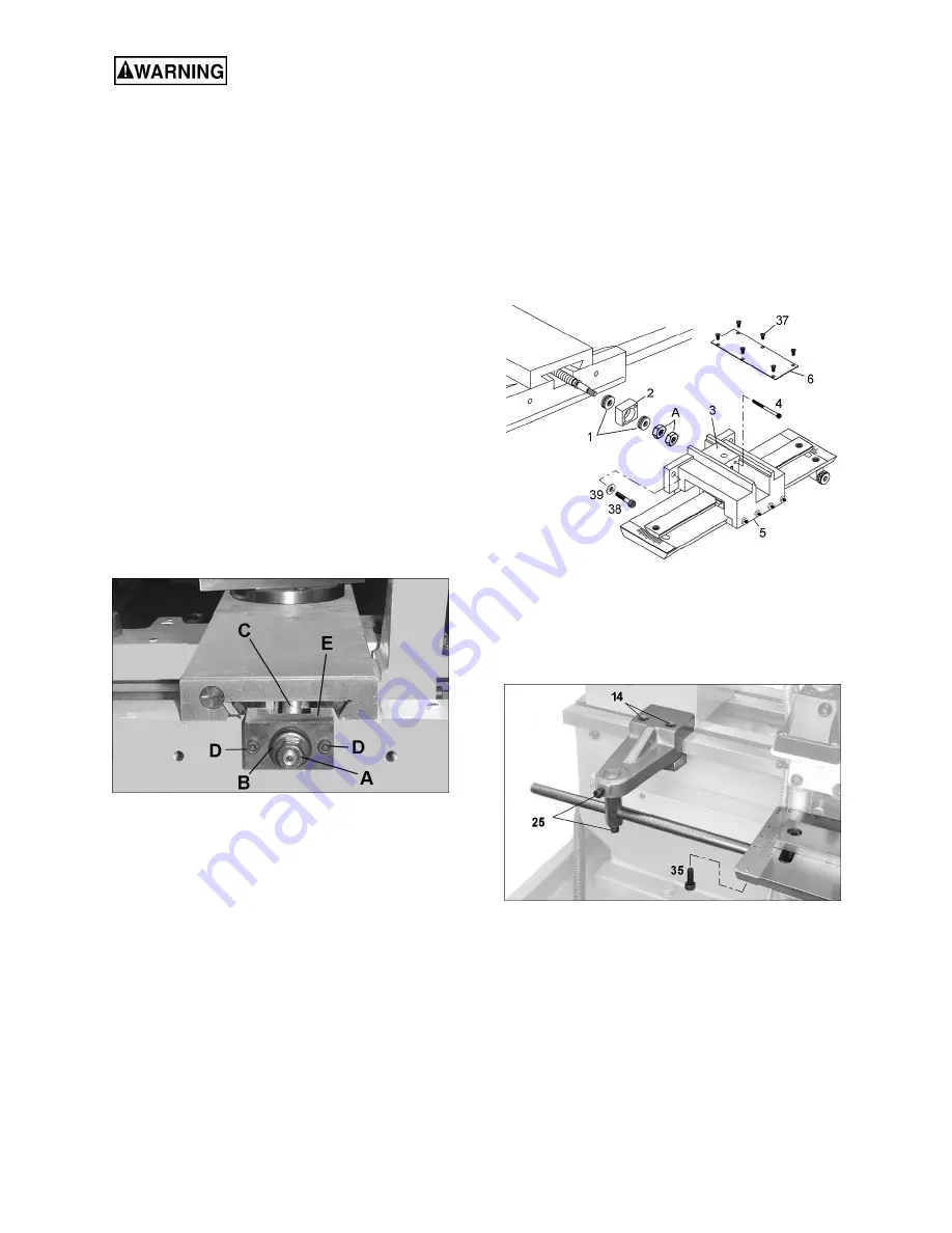
3. Remove two nuts (A, Figure 1) and bearing
cap (B, Figure 1) from end of cross slide screw
(C, Figure 1).
4. Remove the two thrust bearings from cross
feed screw.
5. Remove two hex socket cap screws (D, Figure
1) and the block (E, Figure 1). Set these items
aside; do not discard them.
Figure 1
6. On the taper attachment, remove eight flat
head screws (#37) and remove cover (#6).
See Figure 2.
7. Loosen screws (#4) to separate yoke (#3) from
block (#2).
8. Install block (#2, with thrust bearings #1
installed) onto cross screw. See Figure 2.
9. Reinstall nuts (A, Figure 2) onto end of cross
screw. Tighten inner nut first to snug up
bearing assembly. Turn cross slide handle and
check for smooth rotation. Tighten outer nut to
secure the adjustment.
NOTE: It is recommended that two persons
perform the following steps, one to hold and help
align the taper attachment, the other to secure the
fasteners.
10. Hold taper attachment so that hole in yoke (#3)
aligns with cross screw. Secure yoke to block
(#2) with the two screws (#4).
NOTE: Top surface of block (#2) must be
even
with or lower than
top surface of yoke (#3). If
needed, rotate block (#2) 180-degrees to
achieve this position.
11. Attach base casting (#5) to predrilled holes in
carriage with M8x30 hex socket cap screws,
and flat washers (#38/39, Figure 2). Tighten
the cap screws enough to hold base in position
but loose enough to allow adjustment with
rubber mallet.
Figure 2
12. Install clamp to bedway, along with rod and
pivot, as shown in Figure 3. Secure rod to end
of slide base with screw (#35). Tighten screws
(#14,25,35)
Figure 3
13. Attach a dial indicator with magnetic base to
lathe bed (Figure 4), and level the longitudinal
slide to the bedway. The slide assembly is
level when deviation is less than 0.005” from
end to end. Use rubber mallet or dead blow
hammer to nudge base casting as needed,
until slide is level with bedways.


