background image


8

Assembly 

Base and Column Assembly 

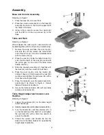
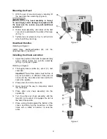
Referring to Figure 1: 

1. Place 

the 

base

 (D) on a level floor. 

2. Place 

the 

column assembly

 (E) on the 

base

 (D) 

and align the holes in the column support with 
the holes in the base. 

3.  Using a 5/8-in wrench, secure the 

column

 (E) 

with four M10 x 30 

hex cap screws

 (O) to the 

base. 

Table and Rack 

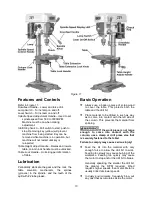
Referring to Figure 2: 

When shipped, the 

rack ring

 (E

1

) and 

rack

 (E

3

) are 

bundled together with the 

column

 (E) in plastic wrap. 

1.  Remove the wrap and take the 

rack ring

 (E

1

and 

rack

 (E

3

) off the 

column

 (E). 

Note which 

end of the rack is up. It must be reinstalled later 
with the same side up.


2. Place 

the 

rack

 (E

3

) inside the table 

bracket

 (C) 

such that the teeth of the 

rack

 (E

3

) mesh with 

the pinion gear on the end of the table crank 
handle 

shaft

 (C

1

). 

3. Slide the 

bracket assembly

 (C) together with 

the 

rack

 (E

3

) onto the 

column

 (E) as shown.  

4. Place 

the 

rack ring

 (E

1

) onto the 

column

 (E), 

sliding it down so it rests against the 

rack

 (E

3

as shown and tighten the 

setscrew

 (E

2

) with a 

3mm hex wrench (provided). 

5. Place 

the 

table

 (B) onto the 

table bracket

 (C), 

positioning it as shown in Figure 2. Secure 
table with 

table


lock handle

 (L). 

6.  Secure the table extension (B

1

) with two 

table 

extension lock knob

s (Q). 

Table Height Adjust and Column Lock 
Handles 

Referring to Figure 2: 

1. Loosen 

the 

setscrew

 (R

1

) on the table 

height 

adjust handle 

(R). 

2. Slide 

the 

handle

 (R) onto the table bracket 

shaft

 (C

1

). 

3. Turn 

the 

handle

 (R) until the 

setscrew

 (R

1

) is 

on the flat section of the 

shaft

 (C

1

) and tighten 

the 

setscrew

 (R

1

) with a 3mm hex wrench to 

secure the handle. 

4. Thread the 

column lock


handle

 (K) into the 

back side of the 

table bracket 

(C) opposite the 

height adjust handle

 (R). 


Figure 1 


Figure 2 


Содержание Bench JDP-12

Страница 1: ...l 12 Variable Speed Drill Press Model JDP 12 WALTER MEIER Manufacturing Inc 427 New Sanford Road LaVergne Tennessee 37086 Part No M 707300 Ph 800 274 6848 Revision A2 03 2012 www waltermeier com Copyright 2012 Walter Meier Manufacturing Inc ...

Страница 2: ...ation postage prepaid to a location designated by us For the name of the location nearest you please call 1 800 274 6848 You must provide proof of initial purchase date and an explanation of the complaint must accompany the merchandise If our inspection discloses a defect we will repair or replace the product or refund the purchase price at our option We will return the repaired product or replace...

Страница 3: ... Cords 10 Adjustments 11 Removing the Chuck and Arbor 11 Adjusting the Depth Stop 11 Spindle Speed Adjust 11 Return Spring Adjustment 12 Laser Adjustment 12 Features and Controls 13 Lubrication 13 Basic Operation 13 Troubleshooting 14 Parts 15 Ordering Replacement Parts 15 Parts List 15 Assembly Drawing 18 Wiring Diagram 19 The specifications in this manual are given as general information and are...

Страница 4: ...often you do this type of work To reduce your exposure to these chemicals work in a well ventilated area and work with approved safety equipment such as face or dust masks that are specifically designed to filter out microscopic particles 10 Do not operate this machine while tired or under the influence of drugs alcohol or any medication 11 Make certain the switch is in the OFF position before con...

Страница 5: ...accessories 28 Disconnect tools before servicing when changing accessories such as blades bits cutters and the like 29 Make sure the work piece is securely attached or clamped to the table Never use your hand to hold the work piece 30 Turn off the machine before cleaning Use a brush or compressed air to remove chips or debris do not use your hands 31 Do not stand on the machine Serious injury coul...

Страница 6: ... Stock Number 707300 Swing 12 Type Bench Top Drilling Capacity 5 8 Chuck Size 5 8 Spindle Travel 3 1 8 Spindle Distance to Base 23 1 2 Spindle Distance to Table max 17 Table Size Diameter width x depth 9 1 2 x 9 1 2 Table Tilt or 45 Spindle Taper MT 2 Column Diameter 2 1 2 Number of Spindle Speeds Variable Range of Spindle Speeds 530 3000 RPM Light Bulb 40W max Overall Height 37 Base Size 11 1 2 x...

Страница 7: ... Q Table Extension Lock Knob 2 R Table Height Adjust Handle 1 Tools Supplied for Assembly M 3mm Hex Wrench N 5mm Hex Wrench Tools Required for Assembly 17mm Box Wrench or a 6 8 Adjustable Wrench Read and understand all assembly instructions before attempting assembly Failure to comply may cause serious injury Before Assembly 1 Remove the contents from the shipping container 2 Compare the contents ...

Страница 8: ...ble crank handle shaft C1 3 Slide the bracket assembly C together with the rack E3 onto the column E as shown 4 Place the rack ring E1 onto the column E sliding it down so it rests against the rack E3 as shown and tighten the setscrew E2 with a 3mm hex wrench provided 5 Place the table B onto the table bracket C positioning it as shown in Figure 2 Secure table with table lock handle L 6 Secure the...

Страница 9: ...t the position of the table to approximately seven inches below the spindle assembly D Fig 3 and lock in place Referring to Figure 4 2 Thoroughly clean spindle A arbor C and chuck D Important These three pieces must be free of any rust protection or lubricant If they are not clean and dry the arbor and chuck will fail to seat in the spindle 3 Place arbor C into the chuck D 4 Open chuck all the way...

Страница 10: ...ed or worn cord immediately 115 Volt Operation Only Referring to Figure 5 As received from the factory your drill press is ready to run at 115 volt operation This drill press when wired for 115 volt is intended for use on a circuit that has an outlet and a plug that looks like the one illustrated in A A temporary adapter which looks like the adapter shown in B may be used to connect this plug to a...

Страница 11: ...holes at the same preset depth use the depth stop as follows 1 Use a pencil to mark A the depth the bit will drill into the workpiece 2 With the drill bit in the chuck lower downfeed handle B to advance bit to your mark A 3 With your other hand advance the lock nut D on the depth stop rod until they are snug to the seat C Tighten E against D 4 The drill bit will now advance to this point 5 To rele...

Страница 12: ...d and any adjustments made before operating the drill press It should also be rechecked periodically as constant machine use may cause it to become misaligned To align refer to Figure 10 1 Place a small drill bit D in the chuck C then place board F flat on the table Do not allow the board to move from this position use clamps if needed Important The drill press table should be in horizontal positi...

Страница 13: ...e and the teeth of the quill with 2 tube grease Basic Operation Always use a back up piece of scrap wood to cover the table This protects both the table and the drill bit Place material to be drilled in such as way as to come into contact with the left side of the column This prevents the material from spinning If the work piece is not large enough to come into contact with the column use a clamp ...

Страница 14: ...bit 3 Dull drill bit 4 Feeding too slowly 1 Change to appropriate speed see speed and pulley chart on page 13 2 Retract drill bit frequently to remove chips 3 Resharpen or replace drill bit 4 Increase feed rate Drill bit wanders 1 Bit sharpened incorrectly 2 Bent drill bit 3 Bit or chuck not installed properly 1 Resharpen bit correctly 2 Replace drill bit 3 Reinstall the chuck or bit properly Wood...

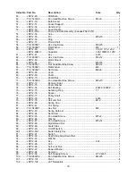
Страница 15: ...rip 1 13 JDP12 13 Crank Arm Shaft 1 14 JDP12 14 Crank Arm 1 15 TS 1523031 Set Screw M6x10 1 16 JDP12 16 Worm Shaft 1 17 JDP12 17 Gear Pin 1 18 JDP12 18 Helical Gear 1 19 JDP12 19 Table Support 1 20 JDP12 20 Table 1 21 JDP12 21 Guide Bar 2 22 JDP12 22 Screw 2 23 JDP12 23 Roller Support 1 24 TS 1534032 Pan Head Machine Screw M6x10 2 25 JDP12 25 Roller 1 26 JDP12 26 Rack 1 27 JDP12 27 Column 1 28 TS ...

Страница 16: ... Shaft Plate 1 71 TS 1533032 Pan Head Machine Screw M5x10 2 72 JDP12 72 Receiver Seat 1 73 JDP12 73 Foam Washer 4 74 JDP12 74 Ball Bearing 60203 6203Z 2 75 JDP12 75 Retaining Ring 17 1 76 JDP12 76 Spacer 1 77 JDP12 77 Pulley Shaft 1 78 JDP12 78 Key 4x60 1 79 JDP12 79 Hex Jam Nut M12 2 80 JDP12 80 Spring Cap 1 81 JDP12 81 Coil Spring 1 82 TS 1540061 Hex Nut M8 2 83 JDP12 83 Spring Retainer 1 84 JDP...

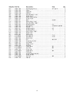
Страница 17: ...12 116 Bracket 1 117 JDP12 117 Retaining Ring 24 1 118 JDP12 118 Retaining Ring 14 1 119 JDP12 119 Motor Pulley Upper 1 120 JDP12 120 Power Cord 1 121 JDP12 121 Motor Cord 1 122 TS 152704 Hex Wrench 3mm 1 123 TS 152705 Hex Wrench 4mm 1 124 JDP12 124 Rack Collar 1 125 JDP12 125 Pin Ø2 5x12 1 126 JDP12 126 Chuck Key Holder 1 127 JDP12 127 Cord Wrap 1 128 JDP12 128 Pulley Cover 1 129 JDP12 129 Drift ...

Страница 18: ...18 Assembly Drawing ...

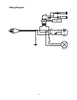
Страница 19: ...19 Wiring Diagram LED Lamp DRO ...

Страница 20: ...20 WALTER MEIER Manufacturing Inc 427 New Sanford Road LaVergne Tennessee 37086 Phone 800 274 6848 www waltermeier com ...

Отзывы: