


19
10.10
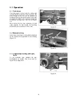
Four-way tool post
The four-way tool post is mounted on the top slide
and allows for tools to be clamped. Loosen the
center clamp handle to rotate any of the four tools
into position (Figure 29).
Use a minimum of two clamping screws when
installing a cutting tool.
10.11
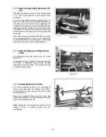
Change Gears
There are eleven gears (Figure 30, 2 pre-mounted
already) with different numbers of teeth (28, 30, 32,
38, 40, 44, 45, 46, 48, 52 and 56). They can be
combined for different speeds and feeds as
required. See chart on headstock.
11.0
Adjustment/replacement
11.1
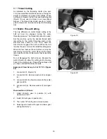
Adjustment of main spindle
bearings
The main spindle bearings are adjusted at the
factory. If end play becomes evident after
considerable use, the bearings may be adjusted.
Loosen setscrew (1, Figure 31) in the slotted nut (2,
Figure 31) on the back of the spindle. Tighten
slotted nut until all end play is taken up. The spindle
should still revolve freely.
Caution:
Excessive
tightening or preloading will damage the bearing
.
Re-tighten set screw (1, Figure 31).
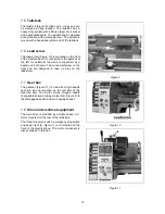
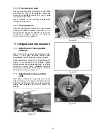
11.2
Adjustment of cross and top
slide
Each slide is fitted with a gib strip and can be
adjusted with screw (1, Figure 32) fitted with lock
nut (2, Figure 32). Loosen the lock nuts to adjust the
screws, and re-tighten lock nuts to secure the
setting.
Figure 32
Figure 29
Figure 30
Figure 31
Содержание 321370K
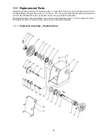
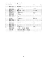
Страница 25: ...25 13 2 1 Drive Belt Assembly Exploded View ...
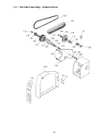
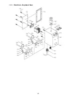
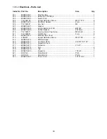
Страница 29: ...29 13 5 1 Electrical Exploded View ...
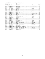
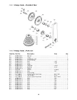
Страница 32: ...32 13 7 1 Gear Box Exploded View ...
Страница 35: ...35 13 8 1 Apron I Exploded View ...
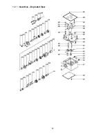
Страница 38: ...38 13 10 2 Saddle and Cross Slide Exploded View ...
Страница 40: ...40 13 11 1 Compound Slide Exploded View ...
Страница 42: ...42 13 12 1 Tailstock Exploded View ...
Страница 46: ...46 13 15 1 BD 919 Bed Assembly Exploded View ...
Страница 48: ...48 13 16 1 BDB 929 Bed Assembly Exploded View ...
Страница 54: ...54 15 0 Speed and threading charts ...
Страница 56: ...56 427 New Sanford Road LaVergne Tennessee 37086 Phone 800 274 6848 www jettools com ...


