background image

20 November 2010, R. Ubic                                            

6


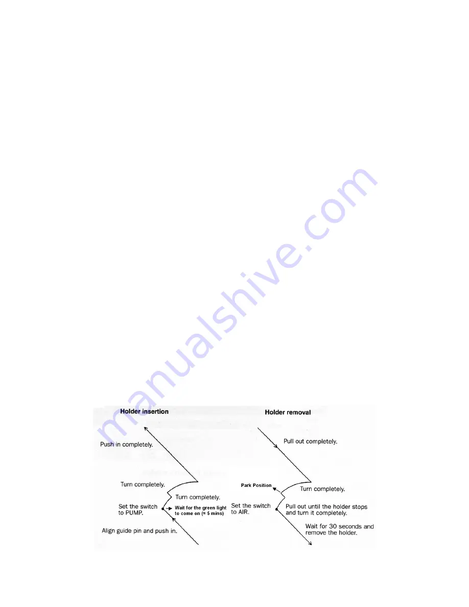
Inserting Specimen Holder into Microscope 

See diagram. 


Ensure that there is no dust or lint on the holder O-rings.  If there is, wipe gently with 

lint-free tissue. 


Ensure that there is sufficient vacuum grease on the O-rings (they should be shiny but 

have no noticeable white traces of grease).  If excess grease is present, wipe it away 

with lint-free tissue. 


Align the specimen holder guide pin with the guide groove in the goniometer.  Push the 

holder into the goniometer until it stops. 


Holding the specimen holder firmly in place, flip the goniometer switch to PUMP.  

The 

yellow light should appear as evacuation commences.


Wait a few minutes for the green light to appear.  

DO NOT ROTATE THE HOLDER 

YET.  

If using the double tilt holder, place the y-tilt control cable on top of the 

goniometer for support.  Do not let the cable dangle. 


Turn the holder clockwise until it stops and insert the holder as far as it will go (not far). 


Turn the holder again clockwise until it stops and insert the holder fully into the column 

until it stops.  

The yellow light on the goniometer will go out at this point.


If using the double tilt holder, plug the y-tilt control cable into the TL-Y socket on the 

goniometer. 


Select the appropriate specimen holder on the top right of the Controller for JEM-

2100/HR main window: 

Single-tilt holder, select EM-21010//21020: Single Tilt Holder.  

Double-tilt holder, select EM-31640: Specimen Tilting Beryllium Holder. 


Ensure that the SIP vacuum gauge recovers to < 2.5 x 10

-5

 Pa before continuing. 


Содержание JEM-2100 HR

Страница 1: ...0 HR TRANSMISSION ELECTRON MICROSCOPE TEM EDS Chemical analysis Post column annular dark field detector Tomography unit for 3D images Cryogenic temperature control down to 77 K Point Resolution 2 3 Li...

Страница 2: ...ow Cooling Water Suspension The high voltage power and lens power will shut down and the vacuum system will go into the protected state Upon resumption of cooling water the microscope must be restarte...

Страница 3: ...mn on left hand side Check to make sure that the gun gas pressure is 0 3 MPa bottom round dial gauge behind grill at base of column on left hand side Check to make sure that the column pressure gauge...

Страница 4: ...ewar with liquid nitrogen For operation at 100 200 kV Use the and buttons to increase the kV setting to 100 kV The Step option allows you to control the step size of the changes Press the HT ON button...

Страница 5: ...tion and secure it with the retainer screws Open the clamp on the holder again with the cartridge handling tool and re insert the cartridge carefully locating it on the pin Double Tilt Beryllium Holde...

Страница 6: ...for the green light to appear DO NOT ROTATE THE HOLDER YET If using the double tilt holder place the y tilt control cable on top of the goniometer for support Do not let the cable dangle Turn the hol...

Страница 7: ...e beam current has reached its normal value kV 10 2 Check that all the apertures are out 3 Check that the spot size is set to 1 use SPOT SIZE knob on left hand panel 4 Decrease the magnification and s...

Страница 8: ...maximize the current density brightness on the screen Press F4 again to de select the gun assignments Condenser Astigmatism Correction Press the COND STIG button left hand panel and use the DEF STIG k...

Страница 9: ...T to shut this wobbler off Condenser Lens Deflection Coil Adjustment Tilt Purity Focus the beam Click on Tilt in the Compensator portion of the Alignment Panel for Maintenance window Click on TiltX in...

Страница 10: ...er portion of the Alignment Panel for Maintenance window Unify the resulting two spots using the DEF STIG X knob If the spot moves off screen reduce the camera length and continue adjusting If the spo...

Страница 11: ...AGE WOBB Y button right hand panel Unify the oscillating image with the OBJ FOCUS knobs right hand panel If the image cannot be unified try correcting for objective astigmatism above Press the IMAGE W...

Страница 12: ...NESS knob Adjust the DIFF FOCUS knob right hand panel to obtain the sharpest pattern Center the pattern by pressing PLA on the left hand console and adjusting position with ShiftX and ShiftY knobs To...

Страница 13: ...indow 4 Move the cross cursor to the center of the screen by clicking on the Center button in the Image Control window 5 Turn the BRIGHTNESS knob fully clockwise 6 Obtain a caustic spot using the OBJ...

Страница 14: ...justing the DEF STIG knobs If the Ronchigram is not circular or if adjusting the OBJ FOCUS knobs make it elliptical press the COND STIG button left hand panel and adjust the DEF STIG knobs accordingly...

Страница 15: ...is perfectly fine or if you want to get more detail in the tomogram you can pick 1 degrees Pay attention to the mag and the at start and when needed track at magnification Rule of thumb here is the la...

Страница 16: ...een if this window is not still open Wait until filament is completely off before extracting the holder Do NOT remove the holder while the filament is turning off Remove sample from holder DO NOT STOR...

Отзывы: