background image

Automatic overload regulator            

Accessories 

Rotational speed display for service and operation.
You can connect an external display on the terminal block X4 to display the actual rotational 
speed.

Technical Data 
 

Nominal voltage

From 12V DC – or 24V DC – on-board system with diesel 
generator set running.

Inputs

Power supply 12V/24V DC via 3 screw terminals;
(without Load-Dump-protection)
Pulses proportional to the rotational speed from a 
proximity switch; including connection terminals for
sensor supply

Output

1 floating changeover contact, current rating 8A

Display

green LED: operating voltage
Yellow LED: input pulses
green LED: relay status
2 red LED: programming

Logic

microcontroller with EEPROM, programmed in Assembler

Accuracy

approx. 1% of programmed rotational speed value

Housing

insulating material with transparent cover, approx. 
130x94mm base, approx. 81mm high with 3 cable glands 
PG 11, protection rating IP 65

Connection

screw terminals up to 4mm² on PCB

Operating temperature

-20°C . . . . +60°C

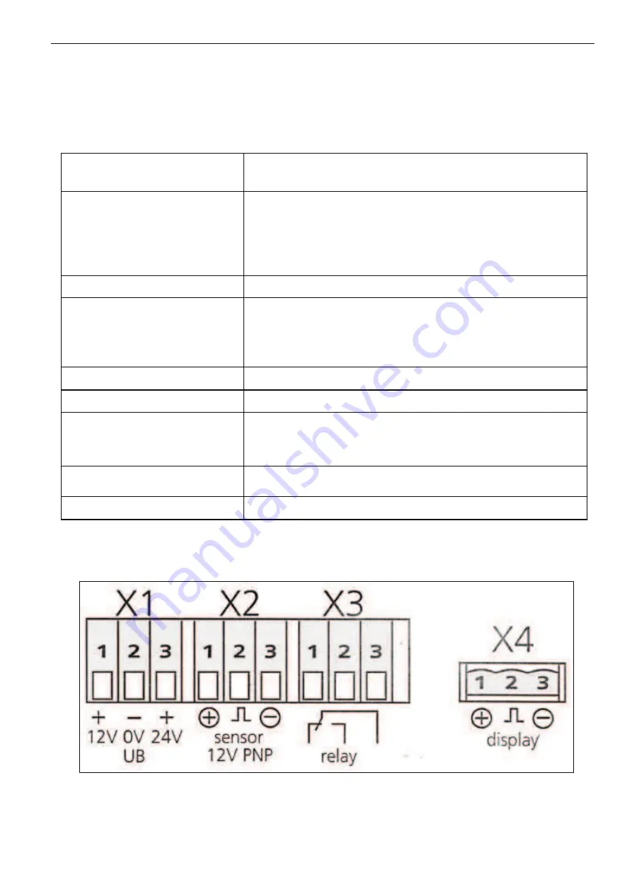
Electrical connection

Disconnect power.
Open transparent front planel and connect the unit as follows:

The unit is equipped with integrated C-Mos components. They can be destroyed by 
electrostatic discharge (ESD). Thus no components except for push-buttons and connection 
terminals may be touched.

Содержание A430 Di

Страница 1: ...n Type A430 DiXL V 2203 Raupe Machine Nr 330505823 Date of building 05 2005 Maasb ll Tel 04634 9370 0 Fax 04634 1025 E mail info jensen service de Jensen ServiceGmbH D 24975 Maasb ll Operating Instruc...

Страница 2: ...ents which we consider to be appropriate An obligation to any previously delivered machines and extended apparatus is nvalid REFERENCE INSTRUCTION This instruction manual also contains descriptions of...

Страница 3: ...elines According to legal provisions the work agreement and the service manual must remain with the machine at all times and must always be available for use When buying renting or borrowing a machine...

Страница 4: ...Di tracked chipper Seriennummer serial number num ro de s rie 330505823 den wesentlichen Sicherheits und Gesundheitsschutz Anforderungen entspricht gem ss der Bestimmung 89 392 EWG und nachfolgenden...

Страница 5: ...lly read operator s manual before handling the machine Observe instructions and safety rules when operating Lire le livret d entretien et les conseils de s curit avant la mise en marche et en tenir co...

Страница 6: ...r l carte de pi ces Zich verwijderd houden van draaiende machinedelen Niemals in den Quetsch Gefahrenbereich greifen solange sich dort Teile bewegen k nnen Never put your hand into the crushing danger...

Страница 7: ...du ch ssis Chassis vooraan Z Fahrgestell vorne Chassis front Avant du ch ssis Chassis vooraan Gefahr durch fort schleudernde Teile bei laufendem Motor Sicherheitsabstand halten Danger flying objects...

Страница 8: ...de wielen aanspannen Alle andere moeren en schroeven regelmatig controleren en desnoods aanpannen Di Fahrgestell vorne Bei Einachs auch hinten Chassis at the frontside For one axle at the backside Ch...

Страница 9: ...s ensure that they are unable to roll away and are protected from unauthorised usage firm brakes activated under wedge in place power source switched off ignition key removed The Wood chipper as culti...

Страница 10: ...down 2 Caution is demanded when in the vicinity of fuel as there is an increased risk of fire Never replenish fuel when near unguarded flames ignition sparks or hot pieces of metal When refulling do n...

Страница 11: ...autions Respect the other parts as well as they may also be not completely safe 4 Never leave the Wood chipper unattended when in use 5 Only operate the machine in good light and good visibility 6 Do...

Страница 12: ...and ensure that they are kept only in approved containers 5 Take care when pouring hot oil as there is a danger of being burnt 6 Take care when removing the cool lid The cooling fluid is kept under pr...

Страница 13: ...f 7 When changing the connections ensure that they are reconnected correctly There is a danger of accidents if they are not e g Forward and backward motions and raising and lowering can be dangerous i...

Страница 14: ...ers of staff The page marked General safety and accident prevention instructions should be read carefully The safety rules for working with the machine are given by the Trade Association General atten...

Страница 15: ...he knife holder bolts are tight and check after 1 hour s work with new or re sharpened knives Before the first use lubricate the feed roller bearings and repeat according to the instructions Ensure th...

Страница 16: ...e blunt or damaged Take great care when removing knives from the machine as the weight of the flywheel can create enough movement to cause injury by trapping fingers even when the tractor is turned of...

Страница 17: ...the A518 20 litres for the A521 A528 A530 23 litres for the A328 A340 27 litres for the A425 A428 A430 60 litres for the A231 A240 64 litres for the A041 141 64 litres for the A10 Oil type HLP ISC fol...

Страница 18: ...ntil disc reaches full operating rotation again then activate feeding again Check all screws and nuts for tightening V belts Check suspense regularly and re tighten if necessary Knives and counter kni...

Страница 19: ...21 13cm A528 15cm A530 15cm On heavy feed please watch the rpm of the chipper disk In case the rpm drops you should disengage the hydraulic feed rollers and do not engage again before the machine is b...

Страница 20: ...depending on wood and engine A141 26cm A141XL 30cm A041 30cm A231 24cm A240 24cm A328 20cm A340 20cm A425 18cm A430 18cm A521 13cm A521XL 15cm A528 15cm A530 15cm On heavy feed please watch the rpm o...

Страница 21: ...07 92 A 328 Z 104 80 A 328 ZUX 103 81 A 340 Di 107 92 A 340 Z 104 80 A 340 ZUX 103 81 A 425 Di 107 92 A 425 Z 104 92 A 521 A528 Di 108 84 A 521 A528 Z 108 88 A 518 Di 106 95 A 518 Z 103 88 Measurement...

Страница 22: ...ng maintenance free 2 maintenance free ball bearing 3 joint weekly 3 2 3 Retinax A lube fitting 4 telescopic section weekly 1 2 3 Retinax A lube fitting 5 bearing maintenance free 1 maintenance free b...

Страница 23: ...Knife grinding overview with wear limit...

Страница 24: ...g on the axis Push one lever forward and the other backward Only for variable tracks Push the second lever from left forward or backward to change the undercar riage width Only for tracks with til bed...

Страница 25: ...d stopping on inclined grounds is very dangerous If you can t help parking or stopping on slopes take the following precautions 1 If the engine races on inclined grounds position all the levers in neu...

Страница 26: ...back up or down again 2 Never actuate any lever excapt for the drive lever when going up or down a ramp Actuating other levers can cause the machine to become unbalanced and tip over 3 There is a sudd...

Страница 27: ...excess pad wear Avoid working on asphalt surfaces when their temperature exceeds 60 C since this causes both excess pad wear and damage to the asphalt surface 4 Maneuvers with a loose track on an irre...

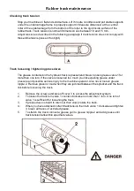
Страница 28: ...n grease valve 1 for more than one turn If the valve is loosened too much you risk expelling grease under pressure and possible serious injury to the machine operator Also never loosen grease nipple 2...

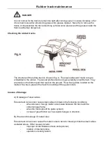
Страница 29: ...They are made on the bottom part that rests on the ground The wheel guides located on the inside of the track prevent the track from sliding off the guide rollers Causes of damage A Breakage of steel...

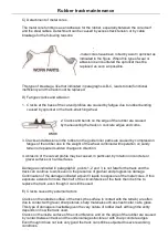
Страница 30: ...ation on sandy terrain or repeated sudden changes in direction 4 Abrasion of the carved profile may be caused in particular by rotation on concrete or gravel surfaces or hard surfaces Damage as indica...

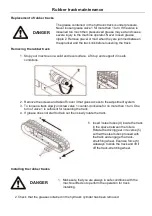
Страница 31: ...at gives access to the adjustment system 3 To loosen a track slowly unscrew valve 1 counter clockwise for no more than 1 turn One turn of valve 1 is sufficient for loosening the track 4 If grease does...

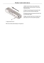
Страница 32: ...ing wheel 4 Rotate the driving gear in erverse 7 and pull the track soles inside the frame 8 5 Position the track using a steel tube and turn the driving gear again 6 Make sure track links mesh correc...

Страница 33: ...5min 5 C 40 C IV 95min 30 C 50 C IV 95min 30 C 65 C IV 165min Every 100 hours check the oil level in the reduction unit gearbox Stop the hydraulic geared motor with plugs aligned horizontal Remove the...

Страница 34: ...5min 5 C 40 C IV 95min 30 C 50 C IV 95min 30 C 65 C IV 165min Every 100 hours check the oil level in the reduction unit gearbox Stop the hydraulic geared motor with plugs aligned horizontal Remove the...

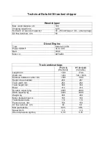
Страница 35: ...rcarriage PT 20 G Standard PT 20 G All Variable Length mm 1740 1740 Width mm 1400 720 1020 Distance between center mm 1390 1390 Height cross member 260 287 Track width mm 250 250 Track height mm 350 3...

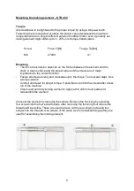
Страница 36: ...ay particular attention to frame components such as track stretching wheels drive geared motors driving gears and guide rollers Make sure these are sdequately tightened according to the following tabl...

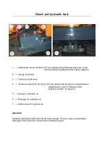
Страница 37: ...r Diesel 4 Hydraulic tank about 48 Liters For any details and hydraulic oil specifications please have a look on Start up of the hydraulic system on page 3 5 Gauge for hydraulic oil 6 Filler pipe for...

Страница 38: ...f maintenance If your machine is equipped with a turntable lubricate it monthly Retinax A until the grease get s out of the gap Both bearings of main shaft pos 1 are filled with lithium grease includi...

Страница 39: ...n grease valve 1 for more than one turn If the valve is loosened too much you risk expelling grease under pressure and possible serious injury to the machine operator Also never loosen grease nipple 2...

Страница 40: ...They are made on the bottom part that rests on the ground The wheel guides located on the inside of the track prevent the track from sliding off the guide rollers Causes of damage A Breakage of steel...

Страница 41: ...ation on sandy terrain or repeated sudden changes in direction 4 Abrasion of the carved profile may be caused in particular by rotation on concrete or gravel surfaces or hard surfaces Damage as indica...

Страница 42: ...at gives access to the adjustment system 3 To loosen a track slowly unscrew valve 1 counter clockwise for no more than 1 turn One turn of valve 1 is sufficient for loosening the track 4 If grease does...

Страница 43: ...ing wheel 4 Rotate the driving gear in erverse 7 and pull the track soles inside the frame 8 5 Position the track using a steel tube and turn the driving gear again 6 Make sure track links mesh correc...

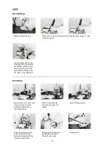
Страница 44: ...atch the holes Screw in the screws loosely Put the pulley on the shaft push it to the correct position and fasten the screws tight and even Remove screws and insert one of them into the hole with the...

Страница 45: ...screws are of major importance to the correct function Fasten all screws evenly and crosswise up to the torque Ta in several steps Use a torque wrench Controll all screws for proper torque If possible...

Страница 46: ...remove bearing bush by light hammer blows onto the yoke or by rotating it Mount cross into yoke Use cross journals to guide bearing needles when inserting bushes Drive in bearing bush until annular g...

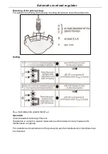
Страница 47: ...nt rating 8A Display green LED operating voltage Yellow LED input pulses green LED relay status 2 red LED programming Logic microcontroller with EEPROM programmed in Assembler Accuracy approx 1 of pro...

Страница 48: ...be adhered to Setting Dmax must always be greater than Dmin Operation Check the safe functioning of the unit If operation is correct no special measures need to be taken nor any measures for maintena...

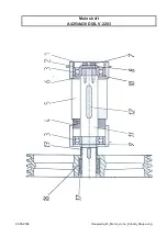
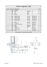
Страница 49: ...Main shaft A425 A430 DiXL V 2203 03 09 2004 Haupwelle_Di_Motor_vorne_Kubota_Raupe eng...

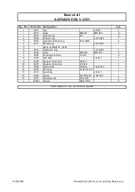
Страница 50: ...protection ring L 47 005 1 1 7 5402 srew M12x35 DIN 933 2 3054 retaining element 12mm 2 8 2333 end disc L 4 07 1 1 9 3326 Seeger circlip ring A55x2 1 10 5407 Seeger circlip ring J120x4 1 11 2585 main...

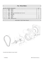
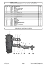
Страница 51: ...r 1 4 714 plate 1 5 16554 Free wheel Stieber 48 mit 4x17 bx 160 1 6 2383 bushing 1 7 15137 fitting key 1 8 5039 screw 12 9 2103 washer 12 10 2104 plate 12 11 16964 bearing journal 1 Parts marked are n...

Страница 52: ...5 mm L35 001 3C 3 6 2678 knife s washer 2 0 mm L35 001 3D 3 6 2679 knife s washer 2 5 mm L35 001 3E 3 7 2665 knife 3 Loch L35 001 3 2 8 2553 knife screw M16x40 DIN 7991 9 9 2690 vertical counter knif...

Страница 53: ...ross and bearing kit 1 14 2301 inboard yoke 1 15 2590 telescopic section inside 1 16 3082 cross and bearing kit 1 17 10014 strain pin 1 18 583 bearing 1 19 3080 hub yoke 1 20 1379 inboard yoke 1 21 10...

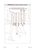
Страница 54: ...A425 A430 Upper and lower retraction roller drive 03 09 2004 Seite 2 Ouwalz_ eng...

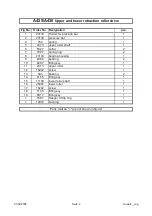
Страница 55: ...r 2 7 7097 spring ring 2 8 23143 bearing housing 1 9 2086 bearing 2 10 6207 fitting key 1 11 2673 upper roller 1 12 16242 screw 1 13 583 bearing 2 14 6155 fitting key 1 15 11100 lower roller shaft 1 1...

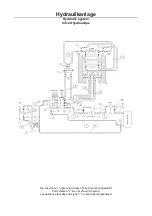
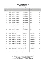
Страница 56: ...mit einem gekennzeichneten Teile sind nicht abgebildet Hydraulikanlage Hydraulic system Circuit hydraulique Parts marked are not shown in figures Les positons pr c d es du signe ne sont pas repr sent...

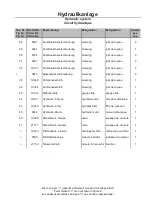
Страница 57: ...Schlauch hydraulic tube tuyeau 2 13 19387 Blockventil block valve block saupape 1 18 21116 Einschraubverschraubung screwing joint de tuyeau 1 20 9686 Einschraubverschraubung screwing joint de tuyeau...

Страница 58: ...de tuyeau 1 40 19192 Me anschlu gauge slide gauge slide 1 42 19477 Hydraulik Pumpe hydraulic pump pompe hydraulique 1 43 19442 Hydraulik Filter hydraulic filter filtre de pression 1 45 9644 Hydraulik...

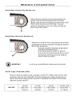
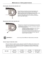
Страница 59: ...free wheel if existing Oil change of the free wheel if existing X Change hydraulic filter cartridge X Check main bearing X Check the condition of the cutting parts and change them if necessary X Oil c...

Страница 60: ...hange oil of the gear box if existing X Check the clearance of the valve X Change fuel filter X Check oil level of the free wheel and top up if necessary if existing Check oil level of the free wheel...

Отзывы: