KTR Kupplungstechnik
GmbH
D-48407 Rheine
C L A M P E X
®
K T R 4 0 0
m o u n t i n g i n s t r u c t i o n s
KTR-N
sheet:
edition:
40818 E
2
2
Gezeichnet: 06.09.01 Sha/Hg
Ersatz für:
KTR-N 40840
Verteiler
Urheberschutz
gemäß DIN 34
Geprüft:
06.09.01 Sha
Ersetzt durch:
W
K
V
VA
M KC
The clamping set is generally delivered in assembled condition.
Tolerances, surfaces
A good rotating process is sufficient:
Highest permissible tolerance:
Rz
≤
16
µ
m
d = h8/H8 - shaft/hub
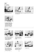
Components of CLAMPEX
®
KTR 400
Component
Quantity
Designation
1
1
front pressure ring (slotted)
2
1
back pressure ring (slotted)
3
1
external ring (slotted)
4
see catalogue cap screw DIN 912
picture 1: CLAMPEX
®
KTR 400
!
C A U T I O N !
Check the clamping set before the assembly, so that the slots of component 1, 2
and 3 are flush with each other.
F
A T T E N T I O N !
Plan a free space between the pressure ring in the back and the hub/shaft for a
later disassembly.
picture 2: free space
for the disassembly
Formula for calculation of the
free space x for the
disassembly:
2
)
B
B
(
x
2
1
−
=
Dimensions for B
1
and B
2
see
CLAMPEX
®
catalogue.
F
A T T E N T I O N !
Dirty or used clamping sets must be disassembled, cleaned and afterwards oiled
with thin-bodied oil (e. g. Castrol 4 in 1 or Klüber Quitsch Ex) before the assembly.


