background image

Содержание JES9750CAB00

Страница 1: ...Downdraft System 19 Complete Installation 21 Moving the Range 21 SI_CURITI_ DE LA CUISINII RE 23 EXIGENCES D INSTALLATION 24 Outils et pieces 24 Exigences d emplacement 24 Exigences concernant I evacu...

Страница 2: ...ese words mean You can be killed or seriously injured if you don t immediately follow instructions You can be killed or seriously injured if you don t follow instructions All safety messages will tell...

Страница 3: ...rical connections be made by a licensed qualified electrical installer IMPORTANT Observe all governing codes and ordinances It is the installer s responsibility to comply with installation clearances...

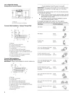
Страница 4: ...m upper cabinet depth B 30 76 2 cm min opening width C For minimum clearance to the top of the cooktop see NOTE D 231 4 59 1 cm opening depth E 30 76 2 cm min opening width E Junction box 5 5 14 0 cm...

Страница 5: ...elbow is used install it as far away as possible from the hood s vent motor exhaust opening Make sure there is a minimum of 18 45 7 cm of straight vent between the elbows if more than one elbow is us...

Страница 6: ...ange for shorter lengths This will cause excessive noise conditioned air loss and affect the flame pattern on gas ranges To convert blower for high range installations see the Install Downdraft System...

Страница 7: ...use with ranges Range Rating Specified Rating of Power Supply Cord Kit and Circuit Protection 120 240 Volts 120 208 Volts Amps 8 8 16 5 KW 7 8 12 5 KW 40 or 50 16 6 22 5 KW 12 6 18 5 KW 50 The NEC cal...

Страница 8: ...are not sure the range is properly grounded Range Rating Rating of Circuit Power Protection Supply Cord 120 240 Volts 120 208 Volts Amps Amps 8 8 16 5 KW 7 8 12 5 KW 40 40 or 50 16 6 22 5KW 12 6 18 5K...

Страница 9: ...r adult can tip the range and be killed Connect anti tip bracket to rear range foot Reconnect the anti tip bracket if the range is moved Failure to follow these instructions can result in death or ser...

Страница 10: ...r obstructions before marking the vent hole location Mark a horizontal line 83 le 20 8 cm from the floor Mark a vertical line up to a maximum of 21 7 9 cm from the right hand side of the cabinet cente...

Страница 11: ...the centerline of the template to the centerline drawn on the floor and place template 21 5 7 cm from the back wall 3 Determine the correct position for the vent hole depending on obstructions joists...

Страница 12: ...ame cabinet as the vent hole opening Top View A 11 27 9 cm from front of cabinet B 14 35 6 cm from left side of cabinet Remove 4 Iocknuts on the motor side of the blower and remove the bracket View fr...

Страница 13: ...ange has been moved into it s final location See Connect Range to Downdraft System section Top View B j_ 8 Position 2 wood spacers and mount them to the floor Top View F iii B_ J A Wood spacers B Moun...

Страница 14: ...rical shock 1 2 3 Disconnect power Use Phillips screwdriver to remove the terminal block cover screw located on the back of the range Pull cover down and toward you to remove cover Remove plastic tag...

Страница 15: ...it plate down and out Position cord conduit plate as shown in the following illustration 5 6 t A Removable retaining nut B Strainrelief Feed the flexible conduit through the strain relief allowing eno...

Страница 16: ...he range Save the ground link screw and the end of the ground link under the screw Feed the power supply cord through the opening in the cord conduit plate on bottom of range Allow enough slack to eas...

Страница 17: ...eter connection opening with ring terminals and marked for use with ranges 5 Replace terminal block access cover Direct Wire Installation Copper or Aluminum Wire This range may be connected directly t...

Страница 18: ...e bare green ground wire to the range with the ground link screw The ground wire must be attached first and must not contact any other terminal 6 Use 3 8 nut driver to connect the neutral white wire t...

Страница 19: ...B Line 1 black C Ground link screw D Bare green ground wire E Line 2 red F Terminal lug 4 Connect line 1 black and line 2 red wires to the outer terminal block posts with 10 32 hex nuts 5 Securely tig...

Страница 20: ...a wrench or pliers to adjust leveling legs up or down until range is level e Push range back into position f Check that rear leveling leg is engaged in anti tip bracket NOTE Range must be level for s...

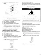
Страница 21: ...Tester Card provided with your range to check the airflow see card for step by step instructions FLOW TESTER j2 72 o _ If there is not sufficient airflow review the Venting Requirements and Venting Me...

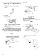
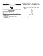
Страница 22: ...wndraft vent system 3 Slide range forward 4 5 Complete cleaning or maintenance To check that anti tip bracket is installed remove access panel and use a flashlight and look underneath the bottom of th...

Страница 23: ...Risque possible de d_cbs ou de blessure grave si vous ne suivez pas imm_diatement les instructions Risque possible de d_cbs ou de blessure grave si vous ne suivez pas les instructions Tous les messag...

Страница 24: ...ite de chaque conducteur Un serre c ble homologation UL Consulter les codes Iocaux Verifier I alimentation electrique existante Voir la section Specifications electriques II est recommande de faire re...

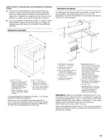
Страница 25: ...imensions du placard Les dimensions de I espace entre les placards correspondent une installation entre des placards de 24 61 0 cm de profondeur avec plan de travail de 25 64 cm de profondeur et de 36...

Страница 26: ...M1601 1 edition 2006 Ne pas installer 2 coudes successifs Ne pas utiliser plus de trois coudes 90 Si un coude est utilise on doit le placer le plus loin possible de I ouverture de decharge du ventila...

Страница 27: ...dia 6 15 2 cm C 16 40 6 cm maximum D Conduit PVC dia 6 15 2 cm pour _gout E Dalle de b_ton F Conduit PVC dia 6 15 2 cm pour _gout G Coud_ _ 90 PVC dia 6 15 2 cm pour _gout H Gravier ou sable compact_...

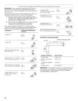
Страница 28: ...e systeme Composant Conduit de diam_tre de 6 15 2 cm Coude 90 de 5 pi 6 15 2 cm vers 3V4 x 10 1 5 m 8 3 cm x 25 4 cm Coude 90 de 3V4 x 10 8 3 cm x 25 4 cm 5 pi 1 5 m Coude plat de 3V4 x 10 8 3 cm x 25...

Страница 29: ...ignaletique On recommande d utiliser un fusible ou un disjoncteur temporis Cette cuisiniere est equip6e d un cordon electrique homologue par la CSA International brancher dans une prise murale standar...

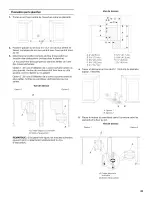
Страница 30: ...Cette operation doit etre effectuee alors que la cuisiniere repose sur sa partie posterieure ou qu elle est supportee par 2 pieds apres avoir ete replacee en position verticale REMARQUE Pour placer n...

Страница 31: ...2 x 1 B Bride antibasculement A I aide d un tournevis Phillips monter la bride antibasculement sur lemur ou sur le plancher avec les deux vis n 12 x 1 fournies D_terminer la Iongueur _quivalente du ci...

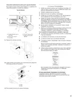
Страница 32: ...droite de I axe central B 83 16 20 8 cm du sol Tracer et decouper un trou de 6W 15 8 cm de diam_tre A _ L i A 6 15 8 cm Placer le ventilateur dans I ouverture entre les placards Raccorder le circuit d...

Страница 33: ...lisation de la zone hachuree avant la plus petite I entree du ventilateur doit faire face au mur arriere Vue de dessus Option 1 Option 2 B A Entree depuis la cuisiniere B Sortie d _vacuation B REMARQU...

Страница 34: ...tant la decoupe du trou d evacuation Vue de dessus A 11 27 9 cm _ partir de I avant du placard B 14 35 6 cm _ partir du c6t_ gauche du placard Devisser les quatre ecrous de blocage du c6te moteur du v...

Страница 35: ...e de dessus A 1 Raccorder le conduit flexible fourni a I entree du ventilateur I aide d une bride pour conduit A B A Conduit flexible d entr_e B Bride pour conduit 2 Verifier la hauteur du plan de tra...

Страница 36: ...Regler I aplomb de la cuisiniere a Placer la grille dans le four b Placer un niveau sur la grille et contr61er I aplomb de la cuisiniere d abord transversalement puis dans le sens avant arriere c Si...

Страница 37: ...ction Entretien de la cuisiniere dans le Guide d utilisation et d entretien 6 Lire la section Utilisation de la cuisiniere dans le Guide d utilisation et d entretien 7 Mettre en marche les brQleurs de...

Страница 38: ...r le bas 2 Faire glisser la cuisiniere vers I avant 3 Debrancher le cordon d alimentation electrique 4 Effectuer le nettoyage ou I entretien 5 Brancher le cordon d alimentation electrique 6 Retirer le...

Страница 39: ...39...

Страница 40: ...eserves Registered Trademark TM Trademark of Jenn Air U S A Used under license by Maytag Limited in Canada Marque deposee TM Marque de commerce de Jenn Air U S A Emploi sous licence par Maytag Limited...

Страница 41: ...Downdraft System 19 Complete Installation 21 Moving the Range 21 SI_CURITI_ DE LA CUISINII RE 23 EXIGENCES D INSTALLATION 24 Outils et pieces 24 Exigences d emplacement 24 Exigences concernant I evacu...

Страница 42: ...ese words mean You can be killed or seriously injured if you don t immediately follow instructions You can be killed or seriously injured if you don t follow instructions All safety messages will tell...

Страница 43: ...rical connections be made by a licensed qualified electrical installer IMPORTANT Observe all governing codes and ordinances It is the installer s responsibility to comply with installation clearances...

Страница 44: ...m upper cabinet depth B 30 76 2 cm min opening width C For minimum clearance to the top of the cooktop see NOTE D 231 4 59 1 cm opening depth E 30 76 2 cm min opening width E Junction box 5 5 14 0 cm...

Страница 45: ...elbow is used install it as far away as possible from the hood s vent motor exhaust opening Make sure there is a minimum of 18 45 7 cm of straight vent between the elbows if more than one elbow is us...

Страница 46: ...ange for shorter lengths This will cause excessive noise conditioned air loss and affect the flame pattern on gas ranges To convert blower for high range installations see the Install Downdraft System...

Страница 47: ...use with ranges Range Rating Specified Rating of Power Supply Cord Kit and Circuit Protection 120 240 Volts 120 208 Volts Amps 8 8 16 5 KW 7 8 12 5 KW 40 or 50 16 6 22 5 KW 12 6 18 5 KW 50 The NEC cal...

Страница 48: ...are not sure the range is properly grounded Range Rating Rating of Circuit Power Protection Supply Cord 120 240 Volts 120 208 Volts Amps Amps 8 8 16 5 KW 7 8 12 5 KW 40 40 or 50 16 6 22 5KW 12 6 18 5K...

Страница 49: ...r adult can tip the range and be killed Connect anti tip bracket to rear range foot Reconnect the anti tip bracket if the range is moved Failure to follow these instructions can result in death or ser...

Страница 50: ...r obstructions before marking the vent hole location Mark a horizontal line 83 le 20 8 cm from the floor Mark a vertical line up to a maximum of 21 7 9 cm from the right hand side of the cabinet cente...

Страница 51: ...the centerline of the template to the centerline drawn on the floor and place template 21 5 7 cm from the back wall 3 Determine the correct position for the vent hole depending on obstructions joists...

Страница 52: ...ame cabinet as the vent hole opening Top View A 11 27 9 cm from front of cabinet B 14 35 6 cm from left side of cabinet Remove 4 Iocknuts on the motor side of the blower and remove the bracket View fr...

Страница 53: ...ange has been moved into it s final location See Connect Range to Downdraft System section Top View B j_ 8 Position 2 wood spacers and mount them to the floor Top View F i ii B_ J A Wood spacers B Mou...

Страница 54: ...rical shock 1 2 3 Disconnect power Use Phillips screwdriver to remove the terminal block cover screw located on the back of the range Pull cover down and toward you to remove cover Remove plastic tag...

Страница 55: ...it plate down and out Position cord conduit plate as shown in the following illustration 5 6 t A Removable retaining nut B Strainrelief Feed the flexible conduit through the strain relief allowing eno...

Страница 56: ...he range Save the ground link screw and the end of the ground link under the screw Feed the power supply cord through the opening in the cord conduit plate on bottom of range Allow enough slack to eas...

Страница 57: ...eter connection opening with ring terminals and marked for use with ranges 5 Replace terminal block access cover Direct Wire Installation Copper or Aluminum Wire This range may be connected directly t...

Страница 58: ...e bare green ground wire to the range with the ground link screw The ground wire must be attached first and must not contact any other terminal 6 Use 3 8 nut driver to connect the neutral white wire t...

Страница 59: ...B Line 1 black C Ground link screw D Bare green ground wire E Line 2 red F Terminal lug 4 Connect line 1 black and line 2 red wires to the outer terminal block posts with 10 32 hex nuts 5 Securely tig...

Страница 60: ...a wrench or pliers to adjust leveling legs up or down until range is level e Push range back into position f Check that rear leveling leg is engaged in anti tip bracket NOTE Range must be level for s...

Страница 61: ...Tester Card provided with your range to check the airflow see card for step by step instructions FLOW TESTER j2 72 o _ If there is not sufficient airflow review the Venting Requirements and Venting Me...

Страница 62: ...wndraft vent system 3 Slide range forward 4 5 Complete cleaning or maintenance To check that anti tip bracket is installed remove access panel and use a flashlight and look underneath the bottom of th...

Страница 63: ...Risque possible de d_cbs ou de blessure grave si vous ne suivez pas imm_diatement les instructions Risque possible de d_cbs ou de blessure grave si vous ne suivez pas les instructions Tousles message...

Страница 64: ...ite de chaque conducteur Un serre c ble homologation UL Consulter les codes Iocaux Verifier I alimentation electrique existante Voir la section Specifications electriques II est recommande de faire re...

Страница 65: ...imensions du placard Les dimensions de I espace entre les placards correspondent une installation entre des placards de 24 61 0 cm de profondeur avec plan de travail de 25 64 cm de profondeur et de 36...

Страница 66: ...n M1601 1 edition 2006 Ne pas installer 2 coudes successifs Ne pas utiliser plus de trois coudes 90 Si un coude est utilise on doit le placer le plus loin possible de I ouverture de decharge du ventil...

Страница 67: ...dia 6 15 2 cm C 16 40 6 cm maximum D Conduit PVC dia 6 15 2 cm pour _gout E Dalle de b_ton F Conduit PVC dia 6 15 2 cm pour _gout G Coud_ _ 90 PVC dia 6 15 2 cm pour _gout H Gravier ou sable compact_...

Страница 68: ...e systeme Composant Conduit de diam_tre de 6 15 2 cm Coude 90 de 5 pi 6 15 2 cm vers 3V4 x 10 1 5 m 8 3 cm x 25 4 cm Coude 90 de 3V4 x 10 8 3 cm x 25 4 cm 5 pi 1 5 m Coude plat de 3V4 x 10 8 3 cm x 25...

Страница 69: ...ignaletique On recommande d utiliser un fusible ou un disjoncteur temporis Cette cuisiniere est equip6e d un cordon electrique homologue par la CSA International brancher dans une prise murale standar...

Страница 70: ...Cette operation doit etre effectuee alors que la cuisiniere repose sur sa partie posterieure ou qu elle est supportee par 2 pieds apres avoir ete replacee en position verticale REMARQUE Pour placer n...

Страница 71: ...2 x 1 B Bride antibasculement A I aide d un tournevis Phillips monter la bride antibasculement sur lemur ou sur le plancher avec les deux vis n 12 x 1 fournies D_terminer la Iongueur _quivalente du ci...

Страница 72: ...droite de I axe central B 83 16 20 8 cm du sol Tracer et decouper un trou de 6W 15 8 cm de diam_tre A _ L i A 6 15 8 cm Placer le ventilateur dans I ouverture entre les placards Raccorder le circuit d...

Страница 73: ...lisation de la zone hachuree avant la plus petite I entree du ventilateur doit faire face au mur arriere Vue de dessus Option 1 Option 2 B A Entree depuis la cuisiniere B Sortie d _vacuation B REMARQU...

Страница 74: ...tant la decoupe du trou d evacuation Vue de dessus A 11 27 9 cm _ partir de I avant du placard B 14 35 6 cm _ partir du c6t_ gauche du placard Devisser les quatre ecrous de blocage du c6te moteur du v...

Страница 75: ...ue de dessus A 1 Raccorder le conduit flexible fourni a I entree du ventilateur I aide d une bride pour conduit A B A Conduit flexible d entr_e B Bride pour conduit 2 Verifier la hauteur du plan de tr...

Страница 76: ...Regler I aplomb de la cuisiniere a Placer la grille dans le four b Placer un niveau sur la grille et contr61er I aplomb de la cuisiniere d abord transversalement puis dans le sens avant arriere c Si...

Страница 77: ...tion Entretien de la cuisiniere dans le Guide d utilisation et d entretien 6 Lire la section Utilisation de la cuisiniere dans le Guide d utilisation et d entretien 7 Mettre en marche les brQleurs de...

Страница 78: ...r le bas 2 Faire glisser la cuisiniere vers I avant 3 Debrancher le cordon d alimentation electrique 4 Effectuer le nettoyage ou I entretien 5 Brancher le cordon d alimentation electrique 6 Retirer le...

Страница 79: ...39...

Страница 80: ...eserves Registered Trademark TM Trademark of Jenn Air U S A Used under license by Maytag Limited in Canada Marque deposee TM Marque de commerce de Jenn Air U S A Emploi sous licence par Maytag Limited...

Отзывы: