background image

8

Gas Supply Line 

Provide a gas supply line of ¾" (1.9 cm) rigid pipe to the 
range location. A smaller size pipe on longer runs may result 
in insufficient gas supply. With LP gas, piping or tubing size 
can be ½" (1.3 cm) minimum. Usually, LP gas suppliers 
determine the size and materials used in the system.

NOTE: Pipe-joint compounds that resist the action of LP gas 
must be used. Do not use TEFLON

®†

 tape. 

Flexible metal appliance connector:

If local codes permit, a new CSA design-certified, 
4 - 5 ft (122 - 152.4 cm) long, 

⁵⁄₈

" (1.6 cm) or 

¾" (1.9 cm) I.D., flexible metal appliance connector may 
be used for connecting range to the gas supply line. 

A ½" (1.3 cm) male pipe thread is needed for connection 
to the female pipe threads of the inlet to the range 
pressure regulator. 

Do not kink or damage the flexible metal tubing when 
moving the range.

Rigid pipe connection: 

The rigid pipe connection requires a combination of pipe 
fittings to obtain an in-line connection to the range. The rigid 
pipe must be level with the range connection. All strains must 
be removed from the supply and fuel lines so range will be 
level and in line.

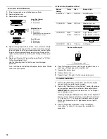
Must include a manual shutoff valve: 
The supply line must be equipped with a manual shutoff 
valve. This valve should be located in the same room but 
external to the range opening, such as an adjacent cabinet. It 
should be in a location that allows ease of opening and 
closing. Do not block access to shutoff valve. The valve is for 
turning on or shutting off gas to the range.

Gas Pressure Regulator

The gas pressure regulator supplied with this range must be 
used. The inlet pressure to the regulator should be as follows for 
proper operation:

Natural Gas:

Minimum pressure: 6" (15.2 cm) WCP

Maximum pressure: 14" (35.6 cm) WCP

LP Gas:

Minimum pressure: 11" (27.9 cm) WCP

Maximum pressure: 14" (35.6 cm) WCP

Contact local gas supplier if you are not sure about the inlet 
pressure.

Burner Input Rating - Altitude

Input ratings shown on the model/serial rating plate are for 
elevations up to 2,000 ft (609.6 m). 

For elevations above 2,000 ft (609.6 m), ratings need to be 
reduced at a rate of 4% for each 1,000 ft (304.8 m). 

Gas Supply Pressure Testing

Gas supply pressure for testing regulator must be at least 
1" water column pressure above the manifold pressure shown 
on the model/serial rating plate.

Line pressure testing above ½ psi gauge (14" WCP)

The range and its individual shutoff valve must be disconnected 
from the gas supply piping system during any pressure testing of 
that system at test pressures in excess of ½ psi (3.5 kPa).

Line pressure testing at ½ psi gauge (14" WCP) or lower

The range must be isolated from the gas supply piping system by 
closing its individual manual shutoff valve during any pressure 
testing of the gas supply piping system at test pressures equal to 
or less than ½ psi (3.5 kPa).

A. Gas supply line
B. Shutoff valve “open” position

C. To range

†®TEFLON is a registered trademark of E.I. Du Pont De Nemours and Company.

A

B

C

Содержание 30" (76.2 cm) Cooktop

Страница 1: ...I RE 26 EXIGENCES D INSTALLATION 27 Outils et pi ces 27 Exigences d emplacement 28 Sp cifications de l installation lectrique 30 Sp cifications de l alimentation en gaz 31 INSTRUCTIONS D INSTALLATION...

Страница 2: ...ath Do not store or use gasoline or other flammable vapors and liquids in the vicinity of this or any other appliance WHAT TO DO IF YOU SMELL GAS Do not try to light any appliance Do not touch any ele...

Страница 3: ...ackguard Order Part Number 8285148 36 91 4 cm Adjustable Backguard Order Part Number 8284756 48 121 9 cm Adjustable Backguard Order Part Number 8284755 9 22 9 cm Backguard for 30 76 2 cm Ranges Order...

Страница 4: ...clearances The anti tip bracket must be installed To install the anti tip bracket shipped with the range see Install Anti Tip Bracket section Grounded electrical supply is required See Electrical Requ...

Страница 5: ...control panel see NOTE C 35 90 2 cm cooktop height when sitting on the wheels D 36 91 4 cm width E Model serial rating plate location A Optional backguard may be installed B 27 68 9 cm depth with cont...

Страница 6: ...EC calculated load is less than the total connected load listed on the model serial rating plate If connecting to a 50 amp circuit use a 50 amp rated cord with kit For 50 amp rated cord kits use kits...

Страница 7: ...NFPA 54 latest edition or CAN CGA B149 latest edition IMPORTANT Range cooktop must be connected to a regulated gas supply IMPORTANT Leak testing of the range cooktop must be conducted according to th...

Страница 8: ...ng and closing Do not block access to shutoff valve The valve is for turning on or shutting off gas to the range Gas Pressure Regulator The gas pressure regulator supplied with this range must be used...

Страница 9: ...range on cardboard to avoid damaging floor InstallOptionalBackguard All ranges may require a backguard See Cabinet Dimensions in the Location Requirements section See the Tools and Parts section for i...

Страница 10: ...cket holes of the determined mounting method See the following Floor Mounting Wall Mounting 4 Using a Phillips screwdriver mount anti tip bracket to the wall or floor with the two 12 x 1 screws provid...

Страница 11: ...ng Use a new 40 amp power supply cord Plug into a grounded outlet Failure to follow these instructions can result in death fire or electrical shock WARNING Electrical Shock Hazard Disconnect power bef...

Страница 12: ...n 7 Tighten strain relief screws 8 Replace terminal block cover 3 wire connection Power supply cord Use this method only if local codes permit connecting cabinet ground conductor to neutral wire of po...

Страница 13: ...equirements section 5 Turn on power supply For further information please refer to the user instructions located in the Use and Care Guide VerifyAnti TipBracketLocation 1 Turn all 4 leveling rods 1 fu...

Страница 14: ...ding pilots When the cooktop control knob is turned to any position the system creates a spark to light the burner This sparking continues until the flame is lit or the knob is turned to Off Check Ope...

Страница 15: ...the burner you want to adjust 8 Turn the control knob to LO and using a butane extension lighter light the burner 9 Remove the control knob 10 Use a x 4 flat blade screwdriver to adjust the flame heig...

Страница 16: ...3 Dispose of recycle all packaging materials 4 For oven use and cleaning read the Use and Care Guide Check Operation of Oven s 1 Turn power on 2 Start a Bake cycle See the Use and Care Guide for oper...

Страница 17: ...re testing above psi gauge 14 WCP The range and its individual shutoff valve must be disconnected from the gas supply piping system during any pressure testing of that system at test pressures in exce...

Страница 18: ...Installation 1 Refer to the Make Gas Connection section for properly connecting the range to the gas supply 2 Refer to the Electronic Ignition System section for proper burner ignition operation and b...

Страница 19: ...ing Gas supply pressure for testing regulator must be at least 1 water column pressure above the manifold pressure shown on the model serial rating plate Line pressure testing above psi gauge 14 WCP T...

Страница 20: ...mplete Installation 1 Refer to the Make Gas Connection section for properly connecting the range to the gas supply 2 Refer to the Electronic Ignition System section for proper burner ignition operatio...

Страница 21: ...iddle 240V Control Wiring Diagram To Cooktop Stand Alone and Freestanding Cooktop Schematics 4 Burner Cooktop R W BK BU W BU W BU W W V W V V W W P2 1 P2 6 P1 1 P1 3 P1 4 P1 6 Griddle Infinite Switch...

Страница 22: ...To Cooktop Stand Alone Version GND G Power Cord Griddle Spare Grill Spare Main Harness Power Spare R W BK W R Reignition Module Cooktop Front View GND BK W BK W W BK BK R N L Control Input Electrodes...

Страница 23: ...R L1 L2 HMI KEYBOARD 15 PIN ATLAS BOARD N LCD BK Y BK OR GY BU BK BK BK Y BK R W Latch Motor 15 PIN Y L2 P7 3 P7 1 Meat Probe Temp Sensor 1654 AT 177 C 350 F V V P2 1 P2 5 W W W W 78k AT 15 6 C 60 F...

Страница 24: ...BU BR BR T OR Strobe P8 6 P8 5 P6 APPLIANCE MANAGER P8 1 P8 3 M W Y BK BK Latch Motor Meat Probe Temp Sensor 1080 At 21 C 70 F 1654 At 177 C 350 F V V P2 1 P2 5 W W W W 78k At 15 6 C 60 F 37k At 32 2...

Страница 25: ...25 Notes...

Страница 26: ...e ou d autres vapeurs ou liquides inflammables proximit de cet appareil ou de tout autre appareil lectrom nager QUE FAIRE DANS LE CAS D UNE ODEUR DE GAZ Ne pas tenter d allumer un appareil Ne pas touc...

Страница 27: ...les doivent tre install s avec un dosseret si l installation se fait sans d gagement entre l appareil et une paroi arri re combustible Voir Dimensions du placard la section Exigences d emplacement pou...

Страница 28: ...r de l emplacement d installation de la cuisini re doivent tre scell es Ne pas r aliser de scellement entre la cuisini re et les placards lat raux Respecter les dimensions indiqu es pour les ouverture...

Страница 29: ...s de l installation des roulettes D 30 76 2 cm de largeur E Emplacement de la plaque signal tique A On peut installer un dosseret facultatif B 27 68 9 cm de profondeur avec le tableau de commande voir...

Страница 30: ...tricit et de tout code ou r glement local en vigueur On peut obtenir un exemplaire de la norme ci dessus aupr s de Canadian Standards Association 178 Rexdale Blvd Toronto ON M9W 1R3 CANADA En cas de d...

Страница 31: ...conversion au gaz propane fournie avec la cuisini re et voir la section Conversions pour changement de gaz Les pi ces pour cette trousse se trouvent dans le sachet de documentation fourni avec la cuis...

Страница 32: ...e Pression minimale 11 27 9 cm colonne d eau Pression maximale 14 35 6 cm colonne d eau En cas d incertitude quant la pression d alimentation tablir contacter le fournisseur de gaz local D bit thermiq...

Страница 33: ...du c t de l emballage sur le plancher derri re la cuisini re 2 personnes ou plus saisir fermement chaque c t de la cuisini re Soulever la cuisini re d environ 3 8 0 cm et la d placer vers l arri re ju...

Страница 34: ...tournevis Phillips monter la bride antibasculement au mur ou au plancher avec les deux vis n 12 x 1 fournies En fonction de l paisseur du plancher des vis plus longues peuvent s av rer n cessaires pou...

Страница 35: ...ases de br leur sur la table de cuisson puis placer les chapeaux de br leur sur les bases de br leur Ensuite placer les grilles de br leur sur les br leurs et chapeaux 4 V rifier que la cuisini re est...

Страница 36: ...soient satisfaisants 1 Placer la grille dans le four 2 Placer un niveau sur la grille et contr ler l aplomb de la cuisini re d abord transversalement puis dans le sens avant arri re 3 Si la cuisini r...

Страница 37: ...emi re fois que l on allume un br leur il peut prendre plus de 4 secondes pour s allumer cause de l air se trouvant dans la canalisation de gaz Apr s avoir v rifi le bon fonctionnement du br leur tour...

Страница 38: ...Tourner le bouton de commande LO faible et allumer le br leur avec un briquet butane allong 9 ter le bouton de commande 10 R gler la hauteur de flamme l aide d un tournevis lame plate de x 4 Serrer la...

Страница 39: ...llage 4 Pour l utilisation et le nettoyage du four lire le Guide d utilisation et d entretien Contr le du fonctionnement du des four s 1 Mettre l appareil sous tension 2 Lancer un programme de cuisson...

Страница 40: ...olonne d eau Pression maximale de 14 35 5 cm colonne d eau Test de pressurisation de la canalisation de gaz On doit tester le d tendeur sous une pression sup rieure d au moins 1 colonne d eau la press...

Страница 41: ...s et conserver le tout avec le sachet de documentation pour pouvoir le r utiliser ult rieurement 7 R installer la base du br leur l aide des deux vis 8 R installer la t te et le chapeau de br leur 9 R...

Страница 42: ...tionnement et le contr le du r glage du d tendeur il faut que la pression d admission au d tendeur corresponde aux indications ci dessous Gaz naturel Pression minimale de 6 15 2 cm colonne d eau Press...

Страница 43: ...lastique et avec les documents fournis avec l appareil pour pouvoir les r utiliser ult rieurement 7 R installer la base du br leur 8 R installer le chapeau de br leur 9 R p ter les tapes 2 8 pour les...

Страница 44: ...cuisson autonome et autoportante Sch mas de la table de cuisson Table de cuisson 4 br leurs R BL N BU BL BU BL BU BL BL VI BL VI VI BL BL P2 1 P2 6 P1 1 P1 3 P1 4 P1 6 Commutateur infini de la plaque...

Страница 45: ...de Sortie des lectrodest Module de rallumage R R R R R R MAR JA VE NEU L R OR JA VE BL BU BU Source secondaire pour la plaque frire Cordon d alimentation uniquement la version de la table de cuisson a...

Страница 46: ...2 1 P2 5 BL BL 78k C 60 F C 90 F P2 6 P2 2 OR t t P1 7 P1 5 P1 4 BR OR TAN BU BU MAR TAN OR R R F M J1 3 J1 4 J2 2 J2 5 J2 4 J2 1 R R BL R R BU BU BU R R M BU OR M M J4 12 J4 11 J4 8 J4 7 OR MAR N N N...

Страница 47: ...12 J4 11 J4 8 J4 7 cran ACL CARTE ATLAS CLAVIER IHM 15 BROCHES 15 BROCHES J900 1 J900 11 ALIMENTATION D COUPAGE SMPS 14 VCC 45 W F F CAPTEUR DE TEMP RATURE 1080 21 C 70 1654 177 C 350 78k C 60 F C 90...

Страница 48: ...its r serv s Registered Trademark Trademark of Jenn Air U S A Used under license by Maytag Limited in Canada Marque d pos e Marque de commerce de Jenn Air U S A Emploi sous licence par Maytag Limited...

Отзывы: