JEI MAGBEAST 2 Скачать руководство пользователя страница 6

JEI SOLUTIONS LTD 


MAGBEAST 2   


Operator’s manual for Drilling Machine

 MAGBEAST 2 

- 5 - 

DO NOT use drill 

on steel thinner than (less than 3/8” (10 mm)). On thin 

steel (less than 3/8” (10 mm)) magnet’s adhesive power would be significantly 
reduced  what  can  cause  machines  failure  or  individuals  injury.  The  machine 

should  be  located  on  the  work  piece  with  the  entire  surface  of  the 

electromagnetic  base!  It  is  recommended  that    each  time,  before  positioning 

the  machine  surface  under  the  electromagnetic  base  should  be  sanded  down 

with  abrasive paper!  


Please keep all recommendations.


II.  START UP AND OPERATION 

1.  Cutters and optional equipment features 


This dril

ling machine’s spindle has a socket with Morse taper 2 which make possible 

to  use  twists  drill  (if  it  necessary  with  using  drill  sleeves)  or  milling  cutters  by  using  AMT 

Arbor for fixing them in socket spindle taper [Drawing 2].  

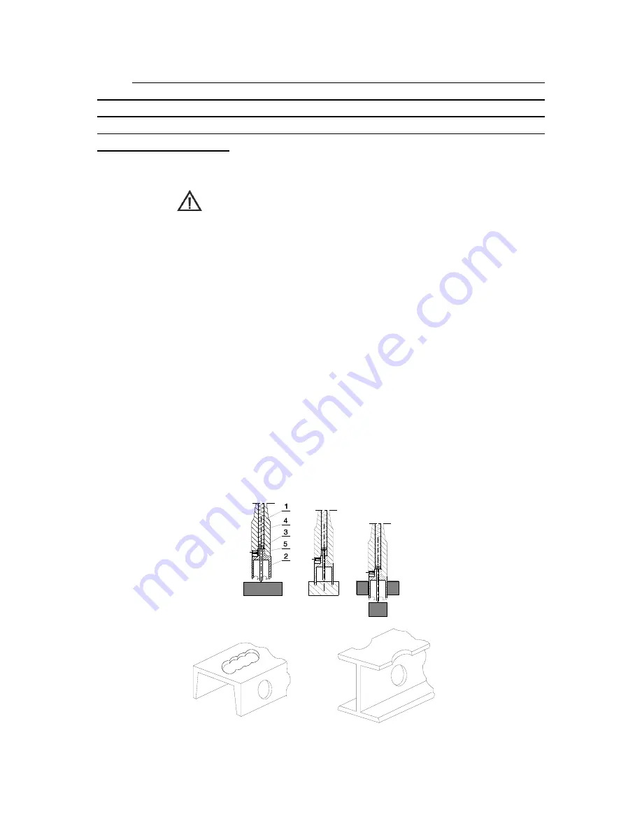
Milling  cutter  (2)  is  located  inside  arbor  body  (1)  and  is  fastened  with  screws  (3). 

While fastening  the cutter  in  the  socket,  be  aware  that  screws  should    be  screwed  tight  so 

that  they  could  not  come  unscrewed.  It  is  important  to  position  the  cutter  in  relation  to  the 

socket in such a way that  fixing flats on the cutter shank are positioned opposite to the fixing 

screws (3). Both fastening screws(3) should be used  to fasten the cutter. Pilot (5) is located 

inside the cutter. It makes it easier to position milling cutter  over  centre of  a planned hole. 

During  drilling  as  the  cutter  goes  deep  into  steel,  the  pilot  moves  back  into  the  arbor  body 

and tightens discharge spring (4). That spring ejects  slug which is a by-product  of milling a 

hole with a centre free cutter. 

Basically milling cutters are designed to make through holes. On occasions when 

there is a need for an overlapping hole  pilot should not be used. [Drawing 3] 


Drawing 3. A few types of holes that can be done with a milling cutter. 

Drawing 2. Principle of milling cutter’s work 


Содержание MAGBEAST 2

Страница 1: ...ESS PARK NEWHALLHEY RD RAWTENSTALL ROSSENDALE LANCASHIRE BB4 6HR UK Tel 44 1706 229490 Fax 44 1706 830496 www jeiuk com e mail sales jeisolutions co uk SAFETY INSTRUCTIONS AND OPERATOR S MANUAL FOR DRILLING MACHINE M MA AG GB BE EA AS ST T 2 2 ...

Страница 2: ...TION 7 1 Cutters and optional equipment features 7 2 Machine start up 10 3 Operating instructions 17 III ADJUSTMENT MAINTENANCE AND SERVICE 18 IV TECHNICAL DATA 19 V ELECTRICAL DIAGRAM 22 VI EC DECLARATION OF CONFORMITY 23 VII MACHINE TEST CERTYFICATE 24 VIII WARRANTY CARD 25 BEFORE YOU START WORK WITH THE MACHINE PLEASE READ THESE INSTRUCTIONS CAREFULLY AND USE ALL RECOMMENDATIONS ...

Страница 3: ...pany military equipment service onboard ship maintenance shop etc But full advantages of electromagnetic drilling machines can be achieved only with optimal tooling Milling cutters are designed and manufactured specifically for use with these machines and offer a whole range of advantages in one pass and with precision not otherwise attainable without heavy stationary equipment The drill is equipp...

Страница 4: ...fe use of drilling machine 1 Before attempting to work with the machine check condition of electrics including power cord and plug 2 The drilling machine should be connected to an installation equipped with protection circuit neutral or ground and protected with a 16 A fuse for 220V and 32 A fuse for 120V When used on building sites it must be supplied through a separation transformer made in the ...

Страница 5: ... ejection spring Do not touch or replace the tool with power source on while electromagnetic base is being used 14 Use tools recommended in Operator s Manual only 15 After use always clean drilling machine from metal chips and coolant 16 Always unplug machine from power supply during any work on the machine 17 In the case that the machine falls on a hard surface from a height is wet or is subjecte...

Страница 6: ...ndle taper Drawing 2 Milling cutter 2 is located inside arbor body 1 and is fastened with screws 3 While fastening the cutter in the socket be aware that screws should be screwed tight so that they could not come unscrewed It is important to position the cutter in relation to the socket in such a way that fixing flats on the cutter shank are positioned opposite to the fixing screws 3 Both fastenin...

Страница 7: ... with the fin on top and place it in the spindle e By turning the arbor align the fin to the appropriate slot in the spindle f Using a light impact from the bottom side drive the arbor into the spindle Uninstalling the arbor a Raise the guard turn the spindle so that the wedge MT opening in the spindle 1 is lined up with the wedge MT opening in the reducer body b Place the wedge MT included as sta...

Страница 8: ...order to attain access to the arbor 4 screws 5 3 Insert the appropriate type of pilot 6 into the milling cutter 7 4 Position the milling cutter 7 with the cutter facing up so that the flat sides of the milling cutter are found facing the screws 5 5 Put the milling cutter 7 into the arbor socket 4 6 Tighten the screws securely 5 Uninstalling the milling cutter 1 Raise the drive and the slide 2 up u...

Страница 9: ...ning the machine on work piece always make sure that Work piece is made of ferromagnetic steel some grades of stainless or acid resistant steel does not conduct magnetic flux thickness of work piece is at least 3 8 10 mm surface of steel under the magnet is flat wipe brush or sand down clean surface where you intended to place the drilling machine so that you remove rust paint dirt etc which would...

Страница 10: ...rning spokes counter clockwise As the pilot starts to sink into the cutter cutting lubricant should start to run down cutters inner wall If there is no liquid flowing down check if the tap is fully opened It may take a few seconds for the cutting lubricant to fill the whole system Turn the motor on Making a hole with a milling cutter should ideally be done in one pass It makes the cutter work bett...

Страница 11: ...is just a general guide and the shown dependence applies to average structural steel Cooling agent is fed gravitationally from a coolant bottle through an arbor to an inside of the metal cutter For horizontal and overhead positions special cooling pastes have to be used 2 5 How to use the special functions There are some factors affecting the value of the clamping force They are as follows thickne...

Страница 12: ...JEI SOLUTIONS LTD MAGBEAST 2 Operator s manual for Drilling Machine MAGBEAST 2 11 Drawing 4 Clamping force depending on the thickness of the substrate and the value gap ...

Страница 13: ...JEI SOLUTIONS LTD MAGBEAST 2 Operator s manual for Drilling Machine MAGBEAST 2 12 ...

Страница 14: ...that the system has been appropriately fixed and the cooling conduit 3 is placed correctly on the coolant coupling 4 the bottle cap should be loosened by 1 3 of a turn in order to deaereate it turn on the valve 9 so that liquid travels to the hose after which the machine can be started see II pt 3 After ending work one must remember to tighten the bottle cap and turn off the valve 9 to prevent liq...

Страница 15: ...r up and down several times so that the pressure strip aligns itself and cancels clearance After carrying out these activities and cancelling clearance tighten screws 2 starting from the middle screw The slider should be located symmetrically relative to the middle screw Next tighten the neighbouring screws 2 moving the slider in the degree necessary for making them visible Then tighten screws 3 u...

Страница 16: ...ox lever To move machine into next drilling spot stop the motor as described above and push the mains switch MAGNET to the position O To change the speed use the gear box lever READ THE WHOLE INSTRUCTIONS MANUAL BEFORE ATTEMPTING TO START UP III ADJUSTMENT MAINTENANCE AND SERVICE Every 50 hours of work or as need arises elimination of excess play in slide guides should be performed The screws are ...

Страница 17: ...r required to enter the code or send the damage part with information about type of drilling machine and power supply Caution In the case that the machine falls on a hard surface from a height is wet or is subjected to other unfortunate events that could affect its technical state work should be terminated immediately and the machine should be sent to service for inspection as soon as possible ...

Страница 18: ... diameter 50 mm Max milling depth 51 mm 2 Insulation Class I Standard adhesive force of electromagnet for steel 7 8 22 mm thick and Ra 1 25 12 000 N Slide stroke 153 mm Machine speeds under load I bieg 200 rpm II bieg 400 rpm Electromagnetic base 90x180x48 mm Length of the power cord 3 0 m Total weight 16 5 kg Noise level 85 dB Surrounding temperature 0 40 C Detailed PARTS LIST of Drilling Machine...

Страница 19: ...3 Take off the motor brushes from the connector 6 using the flat ending 5 of the lead The ending has a safeguard against its sliding down first press the protruding element at the middle of the ending then carefully slide off the ending from the connector 4 Push aside the spring arm 7 pressing down the brush and rest it on the surface of the brush holder 8 and remove the brush 9 5 Inspect brush le...

Страница 20: ... 0 67 14 22 200 The above rate on ordinary quality steel 500N mm2 such as S185 S235JR S275JO and use a sharp tool For steel 700N mm2 like E295 S355N C45 speed should be reduced by about 35 2 Guidelines for grading diameters of twist drills when drilling holes Drilling holes of a diameters greater than 18mm should be carried out by preliminary drilling where a diameter of a first hole should be 0 7...

Страница 21: ...JEI SOLUTIONS LTD MAGBEAST 2 Operator s manual for Drilling Machine MAGBEAST 2 20 V ELECTRICAL DIAGRAM ...

Страница 22: ...ey Rd Rawtenstall Rossendale Lancashire BB4 6HR UK Declare with full responsibility that product MAGBEAST 2 DRILLING MACHINE Which the declaration applies to is in accordance with the following standard s placed below EN 50144 1 EN 55014 and satisfies safety regulations of guidelines 2004 108 EC 2006 95 EC 2006 42 EC Rawtenstall 2009 10 15 ___________________________ David McFadden Managing Direct...

Страница 23: ...al No _______________________ Date of test _______________________ Electric test results Test Result Test with sinusoidal voltage of 1000 V and frequency 50 Hz Resistance of the protective circuit Ω The above mentioned product meets the requirements of safe usage as prescribed in standard IEC 745 Name of tester ____________________ Quality Control____________________ ...

Страница 24: ...ling Machine to be free of defects in material and workmanship under normal use for a period of 12 months from date of sold This warranty does not cover cutters damage or wear arises from misuse accident tempering or any other causes not related to defects in workmanship or material Date of Production Serial No Quality Control Date of Purchase Signature of Seller ...

Страница 25: ......

Отзывы: