2
Introduction:
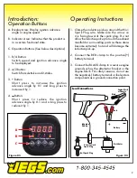
Operation Buttons
1. R/A Button:
Switch speed and ignition advance angle
to be displayed.
2. 4/2 Button:
Switch from 4-stroke and 2-stroke.
3. + Button:
Short press to increase the ignition
advance angle by 0.1 and long press to
increase it by 1.
4. Button:
Short press to reduce the ignition
advance angle by 0.1 and a long press to
reduce it by 1.
Figure 03
A
B
C
A. Display Area: Display ignition advance
angle or engine speed.
B. Indicator Area: Indicates that the product is
in a certain functional state.
C. Operation Buttons (See below descriptions)
1. Clamp the inductive pick-up around the No.1
Spark Plug wire. Make sure the arrow on
it is facing towards the spark plug. Do not
allow the inductive pick-up to touch the exhaust
manifold or surrounding parts as these areas
become extremely hot and will damage the
inductive pick-up.
2. Connect the RED clamp to the po)
battery terminal.
3. Connect the BLACK clamp to a secure engine
ground such as the alternator bracket or the
engine block. For safety reasons, do not use
the negative(-) battery terminal or fuel system
components as a ground connection point.
Black
Red
Battery
+
Distributor
No.1 Spark Plug
Lead Connections
Engine Block
or Chassis
Induction
Pick-Up
Arrow Toward
Spark Plug
Figure 04
Operating Instuctions


