Application Notes
APPLICATION NOTE: Using the ATTENTION Output Line
The intent of this application note is to describe a typical application of the ATTENTION output line of
the SKB interface.
The ATTNENTION (ATTN) line is intended to be used as a mechanism to easily add new devices to
an RS-485 network of SKB switches.
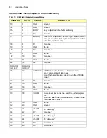
The ATTN line is defined as pin 44 of the 2x25-pin HDD connector on an SKB switch.
An SKB device configured with a device address of 1 (the factory default address) will continuously
assert the ATTN line. The ATTN line is active high.
The ATTN line is an open collector signal that is terminated at the master end only by a 470 Ohms
resistor connected to V+. Upon connection of a terminating resistor, transitions of the line will be
detectable to the master controller.
The ATTN line may be included as part of the network signal harness (or backplane) and connected
to all devices, or may be connected to a single network drop and the master controller.
The operation of the ATTN line is intended to facilitate RS-485 network operation, as follows:
1. At start-up the master should perform a device query (ie. SWITCH or IDN query) through the
entire RS-485 address range (ie. 1 – 31) to determine which addresses have active devices.
This is determined by receipt of a valid response to the query. The master should build a list of
used and unused RS-485 addresses.
2. A new SKB switch (with an address of 1) is added to the RS-485 network and powered-up. This
will cause the ATTN to be asserted.
3. The master recognizes that the ATTN line is asserted, indicating that a device having address 1
has been added to the network.
4. The master assigns the next unused RS-485 address to the device at address 1 (ie
SET_DEVICE_ADDRESS to next unused from the list built in step 1.). This will cause the ATTN
signal to be de-asserted.
5. Additional devices can be added to the network one-by-one in the same fashion, staring at step
2.
6. If there are no unused RS-485 addresses, the SKB configured with address 1 remains at that
address, and the ATTN line will remain asserted.
APPLICATION NOTE: Using the TRIGGER Input Line
The intent of this application note is to define details of the trigger line and to describe a typical appli-
cation.
The SKB interface connector includes a TRIGGER line which can be used to execute a trigger com-
mand.
The trigger command is a standard command packet which is inserted into the command processor
when the trigger line is asserted. The trigger line is asserted by pulling LOW, and the trigger com-
Содержание SKB Series
Страница 1: ...SKB SERIES FIBEROPTIC SWITCH MODULE User Manual ...
Страница 2: ...ii 10109002 Rev 001 August 2001 2001 JDS Uniphase All rights reserved ...
Страница 4: ...iv ...
Страница 11: ...7 Contents ...
Страница 13: ...9 List of Figures ...
Страница 15: ...11 List of Tables ...
Страница 19: ...4 Safety Information Instructions and Symbols ...
Страница 25: ...10 Introduction ...
Страница 53: ...38 Operation and Control Instructions ...
Страница 91: ...76 Commands ...
Страница 111: ...96 Application Notes ...
Страница 113: ...98 Service ...

