


P/N 960-100929R_Rev. 7 {EDP #148849}
© 2017, JAPAN CASH MACHINE CO., LTD.
6 - 7
Calibration and Testing
iVIZION® SeriesNext-Generation Banknote Acceptor Unit
Section 6
Perform the following steps to properly place the
KS-072/KS-089 Calibration Reference Paper into
the iVIZION Unit:
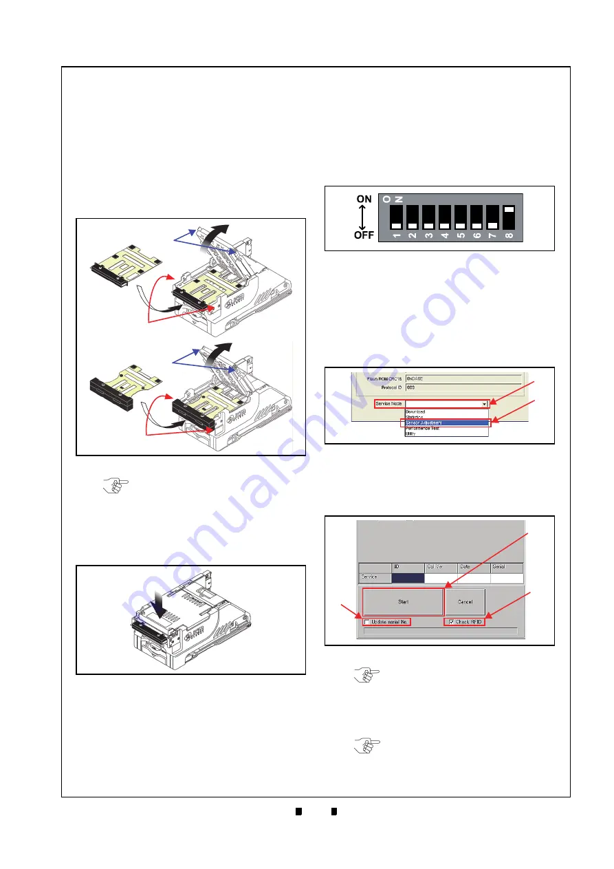
1. Open the Upper Guide while pressing in on the
Upper Guide Access Levers located on each side
of the Acceptor Unit that are indicated by the
Blue
Arrows in Figure 6-28
.
2. Place the KS-072/KS-089 Reference Paper (Fig-
b
) in the Unit until its Catch Edge
reaches both the left and right side of the Frame
c
).
3. Firmly close the Upper Guide (Figure 6-29
a
)
until it “clicks” into place, and ensure that both
sides are tightly closed and locked in place.
Calibration Procedure
The following two (2) methods exist for performing
each of the iVIZION Calibration Procedures:
•
Calibration Only
•
Calibration plus Serial Number Writing.
Calibration Only
Perform the following steps to just calibrate the
iVIZION Unit Sensors:
1. Turn the iVIZION Unit’s Power Switch
OFF
.
2. Set DIP Switch #8 to
ON
3. Turn the iVIZION Unit’s Power Switch
ON
. The
Status LED will begin flashing and then will light
a steady
Blue
Color.
4. Launch the “
JCM Tool Suite Standard Edition
”
Application. The “
JCM Tool Suite Standard Edi-
tion
” Screen shown in Figure 6-31 will appear
when the application becomes active.
5. Click on, and hold-down the “
Service Mode
”
Pull-Down Menu Selection (Figure 6-31
a
) and
slide-down to select “
Sensor Adjustment
” from
within the Pull-Down Menu (Figure 6-31
b
).
6. This action will activate the “
iVIZION Calibration
Ver.X.XX
” Mode automatically, and the Screen
shown in Figure 6-32 will appear.
Figure 6-28
Figure 6-28
Reference Paper Setting 1
a
b
c
a
b
Open
c
KS-072
Reference Paper
KS-089
Reference Paper
NOTE: Place the KS-072/KS-089
Reference Paper so the ID Sticker is
visible, otherwise, Calibration will not
be performed correctly.
Figure 6-29
Reference Paper Setting 2
Figure 6-30
DIP Switch #8 ON
Figure 6-31
JCM Tool Suite Standard Edition
Figure 6-31
JCM Tool Suite Standard Edition
Screen 3
a
b
Figure 6-32
iVIZION Calibration Ver.X.XX Screen
b
c
NOTE: Writing a Serial No. can be
performed after a Calibration is
completed. To do so, Click on the
“Update serial No.” Check-box
b
) if the iVIZION Unit
needs its current Serial No. written.
NOTE: If the RFID Board is not
featured within the iVIZION Unit,
remove the check in the “Check
RFID” Check-box.


