
Important Safety Note:
The
customer is solely responsi-
ble for proper selection of
mounting hardware not
included with the speakers,
and for proper assembly and
installation of the wall-
brackets, including but not
limited to the selection of
appropriate weight-bearing
supports and proper use of
the bracket. JBL disclaims
any liability for the selection
of mounting hardware
and/or bracket installation.
Be sure to follow these
bracket assembly and instal-
lation instructions carefully.
If you have any questions or
doubts about your ability to
correctly wall-mount the
speakers, consult with your
authorized JBL dealer or
custom installer.
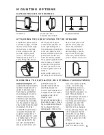
Step 1: Unscrew and remove
the large
Molded Nut
™
. If
necessary, use the supplied
Metal Bar
∞
as a lever by
inserting it into one of the
holes in the outer edge of
the
Molded Nut
™
.
Step 2: Firmly grasp the
Ball
and Shaft
£
and pull it
straight out of the
Attach-
ment Plate
¢
. Avoid leaning
it to the side for leverage, as
this may break off a tab.
Step 3: Slide the
Molded Nut
™
onto the
Ball and Shaft
£
with the threaded open-
ing facing the ball. Thread
the
Metal Nut
¡
all the way
onto the
Ball and Shaft
£
,
with the star washer side
away from the ball. Refer to
the exploded drawing for the
proper orientation of parts.
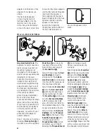
Step 4: Screw the
Ball and
Shaft
£
into the
Threaded
Insert
§
on the back of the
Satellite Speaker
¶
until
it is fully seated in the
Threaded Insert
§
, but
do
not
tighten, as you might
dislodge the
Threaded Insert
§
. Such damage would
not be covered under the
warranty.
Step 5: Tighten the
Metal Nut
¡
with the star washer side
between the
Metal Nut
¡
and the back of the
Satellite
Speaker
¶
, using large
needle-nose pliers, until it is
firmly seated against the back
of the
Speaker
¶
and has
locked the
Ball and Shaft
£
and the
Satellite Speaker
¶
together. Note that once the
Metal Nut
¡
is fully tight-
ened, it may embed some
marks on the back of the
Satellite Speaker
¶
. How-
ever, these marks will be cov-
ered by the
Metal Nut
¡
.
Step 6: Mount the
Attach-
ment Plate
¢
into a wood
stud on the wall, using four
#10 pan-head wood screws
at least one inch long (not
supplied)
•
. Make sure that
all four screws are driven into
the stud and not into drywall.
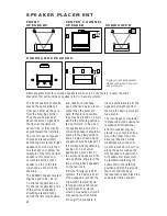
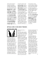
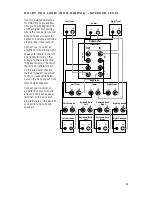
WALL-MOUNTING
1
2
3
4
8
5
1
2
3
4
5
6
7
8
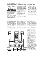
6
adaptor onto the back of the
speaker in two places, as
shown.
The floor stand adaptor
screws may be found in
Hardware Bag B. Use the
larger screw in the upper
screw hole, and the smaller
screw in the lower screw hole.
Screw the floor stand adaptor
into the floor stand’s threaded
insert until the speaker is
firmly attached to the stand.
Back off slightly from the fully
tightened position until the
speaker is oriented as
desired, then rotate the
thumbwheel at the bottom of
the floor stand adaptor to
secure the speaker to the
stand.


