


installation
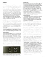
Placement
For optimum source localization within the stereo image, a
pair of 4311s should be arranged so that the listening posi-
tion is centered between the two systems and no more than
30 degrees off-axis horizontally. Vertical orientation should
be treated in a similar manner. (Note: Smoothest frequency
response will be heard from a listening position 15 degrees
off-axis from either unit.) If three or more 4311 s are used, the
enclosures should be angled toward the horizontal center
line of the array to obtain the recommended pattern overlap
at the listening position. If a pair of 4311s are placed horizon-
tally, and fairly close together, a wider stereo perspective will
be realized by orienting the enclosures so that the high
frequency direct radiators are furthest apart. If physically
practical, locating the 4311s so that the high frequency units
are near ear level is generally preferable.
System Connection
Input to the 4311 is via spring-loaded terminal posts located
on the back of the enclosure. The terminals are color coded
to facilitate consistent polarity connection between units in
stereo or multi-channel installations. Eighteen gauge insulated
wire is the minimum size recommended for connections up
to 50 feet. Heavier gauge wire is recommended for greater
distances; 16-gauge from 50 to 100 feet and 14-gauge from
100 to 200 feet.
Important: When connecting or disconnecting loudspeakers from
an amplifier, the amplifier must be turned off. Making connections
while the amplifier is operating could seriously damage the loud-
speaker system and void the warranty.
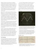
System Adjustment
The frequency dividing network of the 4311 is provided with
front panel controls to allow separate regulation of output in
the 1500 to 6000 Hz "presence" range and the "brilliance"
region above 6000 Hz. Labeled "Presence" and "Brilliance','
the controls are continuously variable from maximum to full
off, with the flattest response (measured in an anechoic
environment) achieved at the midpoints of their travel. With
suitable settings of the two controls, the frequency response
contour of the 4311 can be altered to compensate for almost
any acoustical environment, or to achieve the tonal balance
desired. Control scales are clearly marked from 0 to 10, with
"5" as their midpoints, so that special settings can be logged
and easily reset when needed.
Presence and Brilliance controls are located on the front panel,
below the grille. Flattest response, measured in a laboratory environ-
ment, will be achieved with both controls set at "5:' /
Amplifier Power
The 75-Watt continuous program power capacity of the 4311
is indicative of an "average" program level that can be toler-
ated by the components without damage; however, transients
can exceed this level by a considerable margin without
danger. To achieve the amplifier power reserve necessary
for accurate transient reproduction at high loudness levels,
the 4311 may be driven by amplifiers rated up to 150 Watts
RMS (per channel). Even larger amplifiers can be employed
if normal precautions against input device distortion or
amplifier clipping are followed. For portable installations,
amplifiers having as little output as 10 Watts RMS (per chan-
nel) will drive the 4311 to useable volume levels.
Component Removal
To optimize the sound dispersion characteristics of the loud-
speaker system, maintain the acoustical integrity of the
enclosure and facilitate inspection and service, all compo-
nents mount directly to the baffle panel and are removable
from the front of the enclosure.
Gr/V/e-The grille is secured to the enclosure by hook-and-
pile mounting tape at each corner of the assembly. To remove
the grille, grasp it at the bottom edge and gently lift it from
the enclosure. To replace the grille, reposition it on the en-
closure and apply light pressure at the corners.
Low Frequency—The
low frequency loudspeaker is mounted
with four Phillips-head screws threaded into T-nut fasteners
which are anchored on the back of the baffle panel. After
placing the enclosure on its back on a clean, padded surface,
carefully unscrew the mounting screws without applying
pressure that might dislodge the T-nuts. When the screws
have been removed, gently lift the edge of the loudspeaker
frame from the baffle panel, disconnect the wires at the
terminals and remove the loudspeaker from the enclosure.
Midrange and High Frequency—The
midrange transducer
is held in place by four self-tapping screws at each corner
of its frame. Carefully remove the screws, lift the unit from
the enclosure and disconnect the leads at the terminals. The
high frequency direct radiator is mounted in a similar manner,
with the exception that its input is via tab connectors.
Dividing
Network
-The
dividing network is mounted to the
rear of the baffle and held in place by machine screws extend-
ing through the front of the panel. To gain access to the
network, remove the transducers, pull the wire leads from
the midrange sub-chamber, disconnect the leads at the tab
connectors on the input terminals at the back of the enclo-
sure, carefully peel back the foil nameplate which conceals
the two mounting screws, remove the screws and lift the
network out through the low frequency loudspeaker open-
ing. Note: Malfunction of the network is highly unlikely. Since
the nameplate is generally destroyed during removal, it is
not recommended that the network be removed simply for
the purpose of inspection