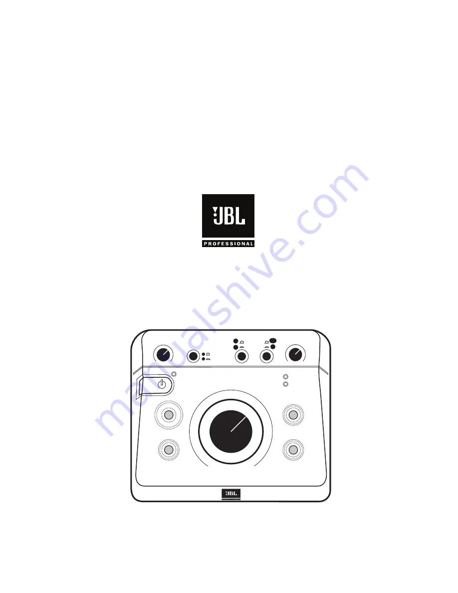
manualshive.com logo in svg
background image

Owner's Manual

HEADPHONE

VOLUME

SPEAKER

SELECT

INPUT

SELECT

INPUT TRIM

POWER

CLIP

SIGNAL

EQ

MUTE

VOLUME

MAX

- ∞

SUB

RMC

A

B

A

B

C

A/B

RMC

MSC1

MONITOR SYSTEM CONTROLLER

MSC1

MONITOR SYSTEM CONTROLLER

MSC

1

MONITOR SYSTEM CONTROLLER

MSC

1

MONITOR SYSTEM CONTROLLER

Document Version: 11.23.2010

by

 HARMAN

Содержание MSC1

Страница 1: ...EAKER SELECT INPUT SELECT INPUT TRIM POWER CLIP SIGNAL EQ MUTE VOLUME MAX SUB RMC A B A B C A B RMC MSC1 MONITOR SYSTEM CONTROLLER MSC1 MONITOR SYSTEM CONTROLLER MSC1 MSC1 MONITOR SYSTEM CONTROLLER Document Version 11 23 2010 by HARMAN ...

Страница 2: ... Control Center Software Windows Operating System 16 To Uninstall the MSC1 Control Center Software 18 Launching the MSC1 Control Center Software Windows Operating System 19 Section 7 Installing MSC1 Control Center Software Macintosh Operating System 20 To Uninstall the MSC1 Control Center Software 22 Launching the MSC1 Control Center Software Macintosh Operating System 23 Section 8 Reference 24 Se...

Страница 3: ... coupler of the power supply cord is used as the ultimate disconnect device from the mains The appliance coupler shall remain readily operable 14 The apparatus shall be connected to mains socket outlet with a protective earthing connection 15 POWER ON OFF SWITCH The power switch DOES NOT interrupt connection to the mains To disconnect the product from the mains remove the power cord connector from...

Страница 4: ...dphone feed to a performer or use headphones in the control room to monitor program material Tailor the frequency response of your speakers using flexible high and low frequency EQ JBL RMC Room Mode Correction With the supplied MSC1 Control Center Software and MSC1 calibration microphone the MSC1 tunes the low frequency response of the speaker system to compensate for inaccuracies measured at the ...

Страница 5: ...hich allows advanced functions such as calibration of the RMCTM Room Mode Correction system adjustment of equalization subwoofer settings and fine speaker alignment including delay and level trim controls Finally we ve included troubleshooting tips and specifications at the end of this manual along with service contact and warranty information Note Throughout this manual important tips and caution...

Страница 6: ...or EQ click the EQ button in the software or press the MSC1 front panel EQ control Make adjustments using the on screen EQ controls To view EQ settings at any time click on the EQ Graph tab 7 To enable MUTE click on the MUTE button in the software or press the front panel MSC1 MUTE control 8 To activate Room Mode Correction RMC settings click the RMC button in the software or press the front panel...

Страница 7: ...ipment Finally a stereo 6 5mm 1 4 inch stereo headphone output with dedicated front panel volume control allows you to send a headphone feed to a performer or monitor audio using headphones in the control room The following illustration shows various suggested MSC1 audio interconnections The use of balanced cabling is recommended when connecting the MSC1 to equipment with balanced inputs and outpu...

Страница 8: ...lly For more information and details about setting the INPUT TRIM control refer to the Front Panel and Rear Panel sections on pages 9 14 of this manual and to the Troubleshooting section on page 20 HEADPHONE VOLUME SPEAKER SELECT INPUT SELECT INPUT TRIM POWER CLIP SIGNAL EQ MUTE VOLUME MAX SUB RMC A B A B B A B RMC 1 2 Minimum Control Not Illuminated C Note Although any audio source may be connect...

Страница 9: ...le 115 115 MSC1 Digital audio workstation with computer audio interface Mixing console MP3 Player RMC Calibration Mic included Headphones A Speaker Subwoofer A Speaker Left Channel A Speaker Right Channel B Speaker Left Channel B Speaker Right Channel ...

Страница 10: ...ot disconnect the power adaptor until all MSC1 front panel indicators are no longer illuminated 3 MSC1 VOLUME Sets the output level for the selected input signal see 6 from full attenuation to MAX 0 dB or no attenuation Note that this control does NOT affect headphone output level see 4 4 HEADPHONE VOLUME Control A dedicated volume control for connected headphones Other than this the only MSC1 con...

Страница 11: ...CLIP LED see 8 below illuminates frequently or steadily reduce the setting of the INPUT TRIM control by turning it counter clockwise When you first use the MSC1 we recommend you take a moment to set the INPUT TRIM control using this procedure 1 Set the INPUT TRIM control to minimum full counter clockwise 2 Set the MSC1 VOLUME control to the 12 00 position 3 Press Play on the device connected to th...

Страница 12: ...Correction When illuminated signal is sent to speakers connected to B SPEAKER OUTPUTS with RMC processing applied See the MSC1 Control Center Software User s Guide Press this button again no illumination to hear the signal without RMC 10 EQ ON Control Activates or deactivates MSC1 EQ available for speakers connected to the A SPEAKER OUTPUT When illuminated an equalized signal is sent to the speake...

Страница 13: ... and the Left and Right speakers play a full range signal Subwoofer Level and Bass Management crossover are set using MSC1 Control Center software Three Bass Management crossover frequencies are provided and the MSC1 ships with an 80 Hz Bass Management crossover selected and subwoofer gain set to 0 dB no additional boost or attenuation See the MSC1 Control Center Software User s Guide Note If your...

Страница 14: ...al Serial Bus connector for computer connection when using the provided MSC1 Control Center software 3 SPEAKER OUTPUTS A B Two pairs of balanced 6 5mm 1 4 inch TRS connectors labeled A and B for connection of two stereo speaker systems Note The processing functions of the MSC1 Room Mode Correction EQ and subwoofer capabilities are only applied to the A SPEAKER OUTPUTS Flat unprocessed signal is ro...

Страница 15: ... headphones to this 6 5mm 1 4 inch stereo jack for private monitoring of the MSC1 output Note For private monitoring of the MSC1 signal over headphones with all speakers off turn the main MSC1 VOLUME control to its fully counterclockwise position and use the dedicated HEADPHONE VOLUME control to set the desired listening level 7 RMC MIC IN Connect the supplied microphone here when performing an RM...

Страница 16: ...t 64 bit Audio Accessible analog audio IN OUT connectors of an internal soundcard or optional external audio interface Directx9 compatible USB Port Minimum Screen Resolution 1024 x 768 Uses MS NET 2 0 Uses Directx 9 0c Uses Adobe Flash 9 or later Uses Adobe Acrobat Reader 7 or later Microsoft Adobe are registered trademarks of their respective owners Harman Professional claims no ownership or good...

Страница 17: ...sted in the MSC1CC Software Installation Screen required to successfully run the MSC1 Control Center The MSC1 Installation Software checks your system and determines the current availability of each component A checkmark appears in the check box adjacent to a given component s launch button if it is determined the component is already installed Therefore a component that has a check mark in its ch...

Страница 18: ...top 10 The Directx 9 0c installation will ask you to choose a directory for the installation Select any location on your C Drive For example create a directory called C directx 9c on your hard drive and select this location for the install 11 The ATMEL FLIP installation will ask you if you want to restart your machine If you select NO then as you exit the MSC1CC Installation you will be reminded t...

Страница 19: ...lied USB cable and powered on Then double click on the desktop icon or single click on the Start menu icon to launch the software See the Features section in the MSC1 CC Software User s Guide for details about all MSC1 Control Center Software display and menu options Your MSC1 must be connected to your computer with the supplied USB cable and powered on before launching the MSC1 Control Center Sof...

Страница 20: ...6 Power PC Intel Audio Accessible analog audio IN OUT connectors of an internal soundcard or optional external audio interface USB port Minimum Screen Resolution 1024 x 768 Uses Adobe Flash 9 or later Adobe Acrobat Reader 9 or later Apple Adobe Intel are registered trademarks of their respective owners Harman Professional claims no ownership or goodwill in the use of these trademarks Note Use on a...

Страница 21: ...ontinue button 6 Read the Introduction and then Continue 7 Review the Read me file for important information 8 Select a destination drive for the MSC1 Control Center Continue 9 Click the CUSTOMIZE button at the bottom of the window After clicking CUSTOMIZE all available software components for installation are listed on this screen All listed components are required Unless a more recent version of...

Страница 22: ...y contacting JBL Professional Customer Service at 800 8JBLPRO 800 852 5776 Monday Friday 8am 5pm P S T To install from downloaded ZIP file 1 Download the correct file for INTEL or POWER PC Macintosh 2 Copy the file to to the desktop 3 Extract the contents using an archive application NOTE To maintain the correct file structure you must use the Extract function of the archive application Proceed to...

Страница 23: ... cable and powered on Then double click on the MSC1 icon to launch the software See the Features section in the MSC1 CC Software User s Guide for details about all MSC1 Control Center Software display and menu options Your MSC1 must be connected to your computer with the supplied USB cable and powered on before launching the MSC1 Control Center Software To protect your speakers it is good practice...

Страница 24: ...ly trim the level of each connected speaker and apply delay to compensate for differences in placement relative to the mix position ensuring balanced mixes regardless of speaker placement Performing an RMC Calibration The supplied MSC1 Control Center software MSC1 Calibration Microphone and accessory cables are required to perform an RMC calibration Refer to the supplied MSC1 Control Center Softwa...

Страница 25: ...ed MSC1 Control Center software Delay and Level Trim Left and Right Speakers and a subwoofer connected to the A SPEAKER OUTPUTS can be level matched and independently delayed to compensate for differences in placement relative to the listening position These adjustments can be made using a computer and supplied MSC1 Control Center software Left and Right speaker levels can be independently attenua...

Страница 26: ...ical power outlet Do not connect equipment with total power requirements that exceed the capabilities the provided power source If after doing this you still hear hum you can try grounding the MSC1 to an available ground source To do this use a Philips head screw driver to loosen the ground screw on the bottom of the MSC1 Attach an insulated wire to the screw and tighten the screw Connect the othe...

Страница 27: ...nfirm that the SPEAKER SELECT switch is set to A EQ affects only signal sent to A SPEAKER OUTPUTS RMC EQ and SUB buttons flash when pressed instead of illuminating steadily The SPEAKER SELECT switch is set to B Processed signal RMC and or EQ and subwoofer signal is heard only when routing signal to A SPEAKER OUTPUTS Only flat unprocessed signal is routed to B SPEAKER OUTPUTS The CLIP LED is illumi...

Страница 28: ...rol and simultaneously press the MUTE control Then release both buttons Completion of the process is confirmed when LEDs on the MSC1 illuminate in a pattern for 15 seconds and the power LED illuminates If after performing Factory Reset the MSC1 is interfaced to a computer and MSC1 Control Center Software is launched the software will offer the option of returning the MSC1 to the settings last stor...

Страница 29: ...Sigma D A Converters 24 Bit 8 times Oversampling Delta Sigma Internal Processing 48 Bit 48 kHz Maximum Input Level 24 dBu 6 5mm 1 4 inch TRS Inputs 12 dBu PHONO RCA Inputs Maximum Output Before Clipping 17 dBu 0 025 THD Input Impedance 20k ohms 6 5mm 1 4 inch TRS Inputs 10k ohms PHONO RCA Inputs Output Impedance 100 ohms Power Requirements 12 VDC 0 5A Dimensions w x d x h 198 x 165 x 83 mm 7 8 x 6...

Страница 30: ...ice must accept any interference received including interference that may cause undesired operation Operation of this unit within significant electromagnetic fields should be avoided Use only shielded interconnecting cables Regulatory Information An example of this equipment has been tested and found to comply with the following European and international Standards for Electromagnetic Compatibilit...

Страница 31: ... Filter parameters L R Mic In Mic Out LEVEL PAD L L R R 6dB 36dB 0dB dB 0 dB dB Mute Mute 0dB 8dB LEDs Enable Balanced 6 5mm inch TRS Inputs 24dBu Max L R Block Diagram Low Freq Shelving Filter High Freq Shelving Filter Left Mixer In EQ Filters Right Mixer In RMC Filters Sub Level 10dB 10dB VOLUME dB to 0dB 3rd order HP Left Channel Right Channel Left Speaker A Right Speaker A Subwoofer A Crossove...

Страница 32: ...jblproservice com Professional Contacts Outside the USA Contact the JBL Professional Distributor in your area A complete list of JBL Professional international distributors is provided at our U S A website www jblpro com En Dehors des Etats Unis Contacter votre Distributeur JBL Professional Une liste complète de nos distributeurs internationaux est disponible sur le site web www jblpro com Interna...

Страница 33: ...pon any misrepresentations by the seller any JBL product on which the serial number has been defaced modified or removed Who Pays For What JBL will pay all labor and material expenses for all repairs covered by this warranty Please be sure to save the original shipping cartons because a charge will be made if replacement cartons are requested Payment of shipping charges is discussed in the next se...

Страница 34: ...ILITY IS LIMITED TO THE REPAIR OR REPLACEMENT AT OUR OPTION OF ANY DEFECTIVE PRODUCT AND SHALL NOT INCLUDE INCIDENTAL OR CONSEQUENTIAL DAMAGES OF ANY KIND SOME STATES DO NOT ALLOW LIMITATIONS ON HOW LONG AN IMPLIED WARRANTY LASTS AND OR DO NOT ALLOW THE EXCLUSION OF INCIDENTAL OR CONSEQUENTIALDAMAGES SOTHEABOVELIMITATIONSANDEXCLUSIONS MAY NOT APPLY TO YOU THIS WARRANTY GIVES YOU SPECIFIC LEGAL RIG...

Страница 35: ......

Страница 36: ...Part Number 444307 001 Rev 11 22 10 JBL Professional 8500 Balboa Boulevard Northridge CA 91329 USA www jblpro com by HARMAN ...

Отзывы: