

4
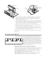
Programming the low-pass filter
Bypass/enable header
To use the low-pass filter, set the jumper on
Jx01 across pins 2 and 3, which are the lower two pins on their header.
But if you do not wish to use the low-pass filter and want to bypass it
instead, set the jumper across pins 1 and 2.
Setting frequency
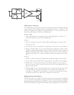
To set the corner frequency (at which the output
is 6 dB down) of the low-pass filter section, choose the appropriate
resistor network value and switch setting for RNx02 and Sx01, respec-
tively. (Sx01 is a
×10
range switch. In its upper position, the frequency
range is ×10; in the lower it is ×1.) Use the low-pass table to select the
right combination. See the appendix of this manual for keys to
identifying the correct resistor network.
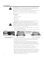
Inserting the resistor network
If there is a resistor network already
installed in the socket, carefully pull it straight out. Insert the pins of
the new resistor network into the socket holes and carefully press the
network into the socket. Be careful to avoid bending the pins of the
resistor network. Orientation of the resistor network is unimportant, as
long as all 8 pins are well seated in the socket.
n
i
1
0
x
S
h
c
t
i
w
S
n
o
i
t
i
s
o
p
"
1
×
"
n
i
1
0
x
S
h
c
t
i
w
S
n
o
i
t
i
s
o
p
"
0
1
×
"
k
r
o
w
t
e
n
r
o
t
s
i
s
e
R
2
0
x
N
R
n
i
z
H
0
8
z
H
0
0
8
K
0
2
1
z
H
0
0
1
z
H
0
0
0
1
K
2
8
z
H
0
2
1
z
H
0
0
2
1
K
8
6
z
H
0
6
1
z
H
0
0
6
1
K
6
5
z
H
0
0
2
z
H
0
0
0
2
K
7
4
z
H
0
5
2
z
H
0
0
5
2
K
3
3
z
H
0
0
5
z
H
0
0
0
5
K
8
1
z
H
0
0
8
z
H
0
0
0
8
K
2
1
z
H
0
0
6
1
z
H
0
0
0
6
1
K
6
.
5
z
H
0
0
0
2
z
H
0
0
0
0
2
K
7
.
4
n
i
2
0
x
S
h
c
t
i
w
S
n
o
i
t
i
s
o
p
"
1
×
"
n
i
2
0
x
S
h
c
t
i
w
S
n
o
i
t
i
s
o
p
"
0
1
×
"
k
r
o
w
t
e
n
r
o
t
s
i
s
e
R
4
0
x
N
R
n
i
z
H
0
2
z
H
0
0
2
K
0
2
1
z
H
0
3
z
H
0
0
3
K
2
8
z
H
0
4
z
H
0
0
4
K
6
5
z
H
0
5
z
H
0
0
5
K
7
4
z
H
0
8
z
H
0
0
8
K
7
2
z
H
0
0
1
z
H
0
0
0
1
K
2
2
z
H
0
2
1
z
H
0
0
2
1
K
0
2
z
H
0
5
1
z
H
0
0
5
1
K
5
1
z
H
0
0
2
z
H
0
0
0
2
K
2
1
z
H
0
0
4
z
H
0
0
0
4
K
6
.
5
z
H
0
0
5
z
H
0
0
0
5
K
7
.
4
z
H
0
0
8
z
H
0
0
0
8
"
K
7
.
2
Programming the high-pass filter
Bypass/enable header
To use either the high-pass filter or the
constant-directivity horn equalization, or both, set the jumper on Jx02
across pins 2 and 3, which are the lower two pins on their header. But
if you do not wish to use either one of these functions and want to
bypass them, then set the jumper across pins 1 and 2.
Setting frequency
To set the corner frequency (at which the output
is 6 dB down) of the high-pass filter section, choose the appropriate
resistor network value and switch setting the RNx04 and Sx02,
respectively. (Sx02 is a
×10
range switch. In its upper position, the
frequency range is x10, in the lower it is ×1.) Use the high-pass table to
select the right combination. See the appendix of this manual for keys
to identifying the correct resistor network.
Inserting the resistor network
If there is a resistor network already
installed in the socket, carefully pull it straight out. Insert the pins of
the new resistor network into the socket holes and carefully press the
network into the socket. Be careful to avoid bending the pins of the
resistor network. Orientation of the resistor network is unimportant, as
long as all 8 pins are well seated in the socket.
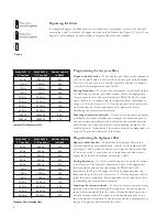
Low-pass filter frequency table
High-pass filter frequency table
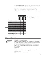
Bypassing the filters
To completely bypass the filter circuitry of a channel, set the jumpers on both Jx01 and Jx02
across pins 1 and 2, which are the upper two pins on their headers (see Figure 6). Note: If you
neglect to place jumpers on either header, no signal will pass on that channel.
Figure 6


