ELITE Series Adjustable Portable Backstop Instructions
- 18 of 32-
JSL-Inst039
www.jayprosports.com
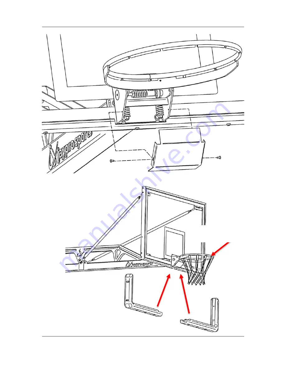
Figure 7-11: Reattach rim cover.
Follow instructions included with Rim to attach net.
Follow instructions included with edge pad.
Страница 1: ...5 14 19 www jayprosports com JAYPRO ELITE SERIES ADJUSTABLE PORTABLE BACKSTOPS Installation and Operating Instructions Applicable Part Numbers Models PBEL66 Jaypro Elite 6600 PBEL96 Jaypro Elite 9600 ...
Страница 2: ...t Rim Height Adjust Leveling Feet 21 Padding Installation 23 Lowering Backstop for Transport 27 Installing Locating Devices 28 Installing Anchor Kit 30 Spring Adjustments 31 Maintenance 32 Safety IMPORTANT LIFT ASSIST SPRINGS UNDER EXTREME TENSION DO NOT ADJUST SPRINGS WITHOUT CONSULTING MANUAL SEE SECTION 14 PAGE 31 IMPORTANT DO NOT REMOVE J HOOK HOLD DOWN CLAMP OR QUICK RELEASE PIN UNTIL THE BAC...
Страница 3: ...s supported on feet Inspect backstop for damage before and after each use Specifications Extension Ballast Standard Backboard Standard Rim Total Weight Jaypro Elite 9600 96 1000 lbs GBRUB 42 42 x 72 GBA 642 2 600 lbs Jaypro Elite 6600 66 800 lbs GBRUB 42 42 x 72 GBA 642 2 400 lbs Jaypro Elite 5400 54 800 lbs1 GBRUB 542 42 x 54 GBA 642 1 600 lbs Introduction This guide describes the installation an...
Страница 4: ...ave the following tools required to complete the installation and setup of your Elite series adjustable portable backstop 1 1 2 Open end Adjustable wrench up to 1 1 2 9 16 Combo wrench 9 16 Socket 2 Phillips screwdriver Level 7 8 Transfer punch recommended 1 1 8 hole saw 1 3 8 hole saw Adhesive suitable for metal to wood bonding Sandpaper 180 320 grit Included Hardware Components Before continuing...
Страница 5: ...Figure 5 3 Locator Pin 2X Figure 5 4 Wire snap safety pin for locator pins 2X Anchor Kit PBELKIT 3 Figure 5 5 FP 89 Floor Anchor 1X Figure 5 6 Cover plate for flaoting wood floors only Figure 5 7 13 Eyebolt w shoulder 1X Figure 5 8 Shackle 2X Figure 5 9 Twisted chain 8 3 Included with PBEL96 optional on PBEL66 see catalog for ordering information ...
Страница 6: ... PBEL66 Figure 5 12 Edge pad 1X model varies Figure 5 13 Adjustable backboard support arm 2X Backboard Rim hardware kit Figure 5 14 Wire Net Tie 1X incl with goal Figure 5 15 Wrench Adjust Pin 1X Each incl with goal Figure 5 16 3 8 x 4 1 2 Hex Bolt 4X Figure 5 17 3 8 16 x 1 1 2 Hex Bolt 2X Figure 5 18 3 8 16 Flanged Hex Nuts 10X Figure 5 19 3 8 Flat Washer 12X Note Disregard fasteners included wit...
Страница 7: ...ge Bolt 4X Figure 5 21 Clevis bracket 4X Figure 5 22 5 8 11 Nylon Hex Nuts 4X Figure 5 23 5 8 Flat Washer 24X Figure 5 24 5 8 11 x 2 1 2 Hex Bolt 4X Figure 5 25 5 8 11 x 6 Left Thread Rod End 2X Figure 5 26 5 8 11 x 6 Right Thread Rod End 2X Figure 5 27 5 8 11 Left Thread Jam Nut 2X Figure 5 28 5 8 11 Right Thread Jam Nut 2X ...
Страница 8: ... com Unpacking IMPORTANT DO NOT REMOVE J HOOK HOLD DOWN CLAMP CARGO STRAP OR QUICK RELEASE PIN UNTIL THE BACKBOARD AND RIM HAVE BEEN INSTALLED FAILURE TO COMPLY MAY RESULT IN SEVERE OR FATAL INJURY AS WELL AS SIGNIFICANT DAMAGE TO SURROUNDING STRUCTURES W A R N I N G J HOOK QUICK PRELEASE PIN ...
Страница 9: ...side of the frame b The front of the unit should now be resting on the wheels c Be careful not to loosen the nuts locking the leveling feet to the threaded rod Use the bottom nut on the leveling foot to raise the leveling feet and the nut on top of the leveling to lower the feet Figure 6 1 Back off Jam nut Figure 6 2 Raise feet using 1 1 2 open wrench 3 Carefully roll backstop off pallet or contai...
Страница 10: ...ATAL INJURY AS WELL AS SIGNIFICANT DAMAGE TO SURROUNDING STRUCTURES 1 Lower wheels until both 2 by 4 s on side of base are level 2 Lower both feet by hand or using a 1 1 2 open or adjustable wrench until they touch the ground 3 Lock feet in place by tightening jam nuts against frame with wrench as in Figure 7 3 4 Raise wheels and confirm base is still level Figure 7 1 Operate jack to lower wheels ...
Страница 11: ...e Backstop Instructions 10 of 32 JSL Inst039 www jayprosports com Figure 7 3 Lock feet w Jam nut Figure 7 4 Raise wheel to level feet 5 Assemble adjustable support arms as shown below note left and right hand threads Do not force it ...
Страница 12: ...d such that the mounting holes in the bottom middle of frame are in line with the bolt pattern on the end of the boom Figure 7 7 Sawhorses or a forklift may be used if additional hands are not available to help not a one person job 7 Insert 3 8 16 x 1 hex bolts 2X 3 8 flat washers 4X and 3 8 flange hex nuts 2X into middle row of holes in backboard mount ...
Страница 13: ...ELITE Series Adjustable Portable Backstop Instructions 12 of 32 JSL Inst039 www jayprosports com Figure 7 6 Backstop boom ...
Страница 14: ... 8 Level the backboard as shown below 9 Attach both adjustable backboard support arms to the slots in boom using the 3 8 16 x 1 carriage bolts 2X 3 8 16 flange nuts 2X as shown in below Figure 7 7 Hand tighten the nuts do not use a wrench Figure 7 7 Install backboard support arms to slots in boom ...
Страница 15: ...into the slots of the top backboard Fasten bolts to backboard using the 3 8 16 x 1 carriage bolts 2X and the 3 8 flanged nuts Wrench tighten all nuts attaching support arms to boom and backboard 11 Check the plumbness of the backboard If it is not plumb twist arms to lengthen or shorten them until the board is plumb ...
Страница 16: ...4 carriage bolts 4X 3 8 flat washers 4X and 3 8 flanged nuts 4X as shown in Figure 7 9 14 Attach rim to board and boom Figure 7 10 15 Ensure that rim is level side to side4 before fully tightening nuts 16 Reattach front cover of rim 17 Follow instructions included with rim to attach net Figure 7 8 Remove front rim cover 4 Level rim front to back using adjusting bushing in board ...
Страница 17: ...ELITE Series Adjustable Portable Backstop Instructions 16 of 32 JSL Inst039 www jayprosports com Figure 7 9 Insert hardware Figure 7 10 Attach rim to board and boom 3 8 x 4 Carriage Bolt ...
Страница 18: ...ELITE Series Adjustable Portable Backstop Instructions 17 of 32 JSL Inst039 www jayprosports com Adjust hex nuts on backboard to plumb rim Make sure top of rim is inline with target Rim Target ...
Страница 19: ...es Adjustable Portable Backstop Instructions 18 of 32 JSL Inst039 www jayprosports com Figure 7 11 Reattach rim cover Follow instructions included with Rim to attach net Follow instructions included with edge pad ...
Страница 20: ... PINNED AT GAME HEIGHT USING THE SUPPLIED QUICK RELEASE PIN WARNING UNIT MUST BE PINNED IN POSITION USING SUPPLIED QUICK RELEASE PIN AT ALL TIMES UNLESS RAISING OR LOWERING WARNING WHEN RAISING OR LOWERING DO NOT RELEASE HANDLES UNLESS BACKSTOP IS PINNED IN POSITION WITH THE SUPPLIED QUICK RELEASE PIN 1 ONLY IF BACKBOARD HAS BEEN INSTALLED remove quick release pin from height adjuster mechanism Fi...
Страница 21: ... J Hook 3 Remove any remaining protective wrapping and or cargo strap from the frame Be careful to not scratch the powder coated finish if using a box cutter or other sharp object 4 ONLY IF BACKBOARD IS INSTALLED remove the quick release pin from the height adjuster mechanism Figure 8 1 5 Stand to one side of the unit and lift one of the two handles on the lower upright Figure 8 4 a If raising the...
Страница 22: ...a hard stop and will be fully vertical c Insert the quick release pin into the height adjuster Set Rim Height Adjust Leveling Feet 1 With backstop in fully raised position lower wheels until both 2 by 4 s on side of base are level 2 Lower both feet by hand or using a 1 1 2 open or adjustable wrench until they touch the ground 3 Lock feet in place by tightening jam nuts against frame with wrench as...
Страница 23: ... 1 1 2 open wrench Figure 9 3 Lock feet w Jam nut Figure 9 4 Raise wheels 5 Verify that the top of the rim is 10 feet off the ground d If the rim is not at 10 feet adjust both feet be sure to maintain level side to side until it is 6 With the backstop still set to 10 verify that the board is still plumb If not adjust according to the procedure in section 7 step 11 ...
Страница 24: ...he quick release pin when pulling the pin never reach across to the other side of the upright to pull the pin 8 Pin the unit in the lowered transport position 9 Raise the feet until both feet are off the ground and the unit rolls freely on all four wheels Padding Installation Padding should be installed ONLY AFTER the foot heights have been set see section 8 above 10 1 Included Padding Hardware Fi...
Страница 25: ... Screw 1 4 20 x 5 8 34X 10 2 Padding Installation 1 Install the front pad a Upright will need to be reclined to one of the intermediate height positions to allow the L clips to fit on top of the 2 x 4 front rail Figure 10 7 L Clips and U Clips fastened to the front pad b Fit the pad onto the top horizontal 2x4 using the fastened L Clips c Secure the front pad to the bottom front with C Clips ...
Страница 26: ...ads a Install L clips to side pads as shown in Figure 10 8 b Fit the pad onto the top horizontal 2x4 using the fastened L Clips c Secure the side pad to the with C Clips attach to the frame Figure 10 8 Install side pads to frame using straps and L Clips Figure 10 9 Install side pads to frame using U Clips and L Clips U Clips L Clips ...
Страница 27: ...ons 26 of 32 JSL Inst039 www jayprosports com 1 Install pads with backstop at 10 0 height 2 Install the upright pad s as shown below w Phillip screws straps Figure 10 11 PBEL96 66 upright pads Figure 10 10 X Clip 3X Webbing straps with plastic buckle 4x ...
Страница 28: ...obstacles such as thresholds 2 Remove quick release pin from height adjust mechanism 3 Stand to one side of the unit and pull one of the two handles on the lower upright Figure 8 4 a If lowering the backstop is too strenuous obtain assistance before attempting to raise b Be sure to maintain control of the uprights while lowering Do not release handle while lowering 4 Reinsert quick release pin to ...
Страница 29: ...aseline 48 b Use the transfer punch or a marker to locate holes for locator bushings using the holes for the alignment pins as guides c Locate hole for floor anchor such that there will be some slack in the chain when installed to anchor point at rear of PBEL base frame Refer to section 13 for anchor kit installation 2 Drill the holes for the locating bushings using the 1 1 8 hole saw Drill all th...
Страница 30: ...ITE Series Adjustable Portable Backstop Instructions 29 of 32 JSL Inst039 www jayprosports com Figure 12 1 PBEL66 Locating and anchor holes locations Figure 12 2 PBEL96 Locating and anchor holes locations ...
Страница 31: ...d with kit for details For installation in floating wood floors ONLY unscrew the top plate from the FP 89 floor anchor Figure 13 1 and install with the brass cover plate Figure 5 7 Refer to FP 100 installation instructions included with kit for details For all floor types locate holes for floor anchors according to the appropriate diagram a PBEL66 66 overhang refer to Figure 12 1 b PBEL96 96 overh...
Страница 32: ...cteristics of the springs are maintained 1 Use a pair of 15 16 combo wrenches or 15 16 deep socket wrench for spring adjustments 2 You will need to place a steel rod in the eye of the eyebolt to which the springs are attached inside face of rear horizontal 2x4 to prevent the eyebolt from rotating as you adjust the nuts 3 Loosen and back off all five jam nuts but do not remove 4 If the unit raises ...
Страница 33: ...and base The springs in particular the areas of the hooks The backboard frame The rim housing Lubrication should be applied to the bronze bushings and the spring contact points once a season or when normal raising lowering of the backstop creates excessive noise Doublecheck that the board and rim are level and plumb and verify that all bolted connections are well fastened If you require additional...