background image

14                                                                                                                                                                             

www.javad.com

...Setup JLink LTE to provide RTK data 

received via UHF channel (in Satel mode) 

to Serial Port

1. Connect to JLink LTE via web interface as de-

scribed above.

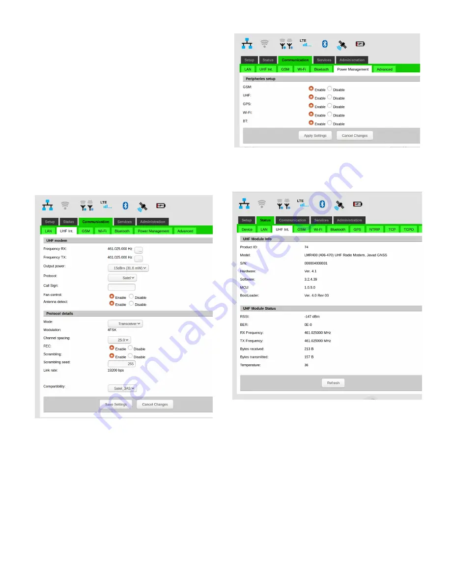
2. UHF configuration in Satel mode:
•  In the

 Communication/UHF Int. 

tab:

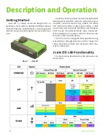
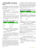
•   select operating frequency or add new fre-

quency to the list

•   select Protocol type Satel

•   select channel bandwidth (spacing) either 

25.0 or, 20.0, or 12.5 kHz

•   verify FEC (Forward Error Correction) state is 

correct

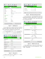
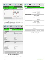
Figure 17. 

 UHF parameters configuration tab

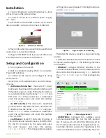
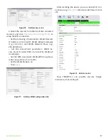
In the 

Communication/Power Management

 tab acti-

vate the UHF interface:

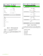
Figure 18. 

Power Management tab

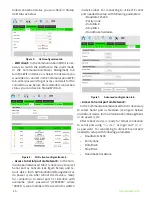
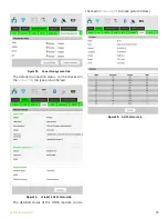
The detailed connection status can be checked in 

the 

Status/UHF int.

 tab 

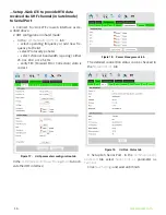
Figure 19. 

 UHF Int. Status tab

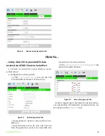
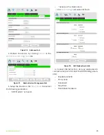
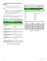
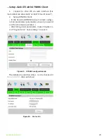
3. Setup teh Serial Port. In the 

Communication/

Advanced

 tab select 

Serial port as

 parameter as 

Terminal

.

Click 

Save Settings

 and wait until finish.

Содержание JLink LTE

Страница 1: ...ghts reserved The information contained herein may not be used accessed copied stored displayed sold modified published or distributed or otherwise reproduced without express written consent from JAVAD GNSS JLink LTE User Manual Version 1 2 Last Revised July23 2020 ...

Страница 2: ... JAVAD GNSS Inc 2020 www javad com ...

Страница 3: ...ceived via NTRIP Client to Serial Port 11 Setup JLink LTE to provide RTK data received via UHF channel in Satel mode to Serial Port 14 Configure TRIUMPH 2 and JLink LTE to provide TRIUMPH 2 services through Internet 16 Update firmware of HPT435BT JL 18 Setup JLink LTE internal GNSS module 18 Setup JLink LTE with external GNSS via network 20 Setup JLink LTE Ethernet Bridge 21 Setup JLink LTE to pro...

Страница 4: ...4 www javad com ...

Страница 5: ...BILITY OR FITNESS FOR ANY PARTICULAR USE OR PURPOSE JAVAD GNSS AND ITS DISTRIBUTORS SHALL NOT BE LIABLE FOR TECHNICAL OR EDITORIAL ERRORS OR OMISSIONS CONTAINED HEREIN NOR FOR INCIDENTAL OR CONSEQUENTIAL DAMAGES RESULTING FROM THE FURNISHING PERFORMANCE OR USE OF THIS MATERIAL OR THE JLINK LTE SUCH DISCLAIMED DAMAGES INCLUDE BUT ARE NOT LIMITED TO LOSS OF TIME LOSS OR DESTRUCTION OF DATA LOSS OF P...

Страница 6: ...ion This equipment has been tested and found to com plywiththelimitsforaClassBdigitaldevice pursuant to Part 15 of the FCC rules These limits are designed to provide reasonable protection against harmful in terference in residential installations This equipment generates uses and can radiate radio frequency en ergy and if not installed and used in accordance with the instructions may cause harmful...

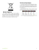
Страница 7: ...d settings you have speci fied This is normal and not a cause for concern Technical Assistance If you have a problem and cannot find the informa tion you need in the product documentation contact your local dealer Alternatively request technical sup port using the JAVAD GNSS World Wide Web site at www javad com To contact JAVAD GNSS Customer Support use the QUESTIONS button available on the www ja...

Страница 8: ...where no cell phone cover is available JLink LTE devices may contain 1 W either UHF 406 to 470 MHz or VHF 138 174 MHz or ISM license free USA band 902 928 MHz and European CEPT license free 868 870 MHz radio transceiver Marine Radiobeacon receiver 283 5 to 325 kHz can be built in into JLink LTE device JLink LTE can be configured and supported using web interface through Internet and this makes the...

Страница 9: ...he device PC handheld pad should be with WiFi interface JLink LTE Wi Fi interface has the name Jlink LTE and pass word testtest When connection is established open the web browser and enter the address 10 1 10 1 8080 via Ethernet JLink LTE LAN static IP adress is 192 168 0 200 and network mask is 255 255 255 0 On the PC connected to the same LAN open the web browser and enter the address 192 168 0...

Страница 10: ... Administration Management or do power cycle After reboot the device is ready for connection to serial port CLI interface with username jlink password jLTEXXXXX where XXXXX is serial number of device which is written in device label For connecting to JLink LTE serial port needed to setup with following parameters Baudrate 115200 Parity none Data Bits 8 Stop Bits 1 Handshake hardware Figure 7 Advan...

Страница 11: ...parameters if necessary Figure 9 GSM configuration tab Use tweezers to install or remove the micro SIM card Insert the SIM card to its slot The first slot from the green top cover is for microSIM the second slot is for microSD card In the Communication Power Management tab activate the GSM interface Figure 10 Power Management tab Wait for registering in the network and Internet ac cess availabilit...

Страница 12: ...lick Save Settings and wait until finish Figure 12 Advanced tab 4 Reboot the device by clicking Reboot in the Administration Management tab Figure 13 Administration Management tab 5 Set up the Router In the Setup Router tab select following parameters NTRIP Client as Source and Serial port as Destination Click Save Setting but ton and wait until finish Figure 14 NTRIP Data Router tab 6 Setup NTRIP...

Страница 13: ...tpoint Click Save Settings and wait until finish The de tailed connection status can be checked in Status NTRIP tab Figure 16 Status NTRIP tab 7 Connect the Serial Port Use any application to connect serial port of JLink LTE with following param eters Baudrate 115200 Parity none Data Bits 8 Stop Bits 1 Handshake hardware ...

Страница 14: ...pe Satel select channel bandwidth spacing either 25 0 or 20 0 or 12 5 kHz verify FEC Forward Error Correction state is correct Figure 17 UHF parameters configuration tab In the Communication Power Management tab acti vate the UHF interface Figure 18 Power Management tab The detailed connection status can be checked in the Status UHF int tab Figure 19 UHF Int Status tab 3 Setup teh Serial Port In t...

Страница 15: ...the Router In the Setup Router tab select the following parameters UHF Modem as Source Serial port as Destination Click Save Settings and wait until finish Figure 22 UHF Modem Router tab 6 Connect the Serial Port Use any application to connect serial port of JLink LTE with following param eters Baudrate 115200 Parity none Data Bits 8 Stop Bits 1 Handshake hardware ...

Страница 16: ...he Status WiFi tab The JLink LTE provides the port forwarding mecha nism from internet GSM interface to WiFi clients Port forwarding mechanism works in a following way JLink LTE receives data from internet and redirects it to its WiFi clients Data packets received by 1110 1119 ports will be redirected to Wi Fi client which IP ad dress is 10 1 10 110 Data packets received by 1120 1129 ports will be...

Страница 17: ... WLAN Network Mask e g 255 255 255 0 Set the AccessPoint parameters WLAN Ac cess Point ID enter SSID of JLink LTE WLAN AP mode wpa Set the WPA parameter WLAN WPA Passphrase enter passphrase of JLink LTE Set the WLAN Mode to on Click Apply Figure 27 NetView WLAN configuration tab After restating the device you can check WiFi con nection using Status WiFi tab of web interface of JLink LTE Figure 28 ...

Страница 18: ...shed Figure 30 FW update tab 4 Reboot the Modem in the Administration Management tab click Reboot After the reboot is complete the device is ready for use Figure 31 Management tab Setup JLink LTE internal GNSS module 1 Connect to Jlink LTE via web interface 2 If using GNSS Base or Assisted modes is necessary to insert the SIM card 3 GSM GNSS configuration in the Communication GSM tab see picture b...

Страница 19: ...t tab The detailed connection status can be checked in the Status GSM tab see picture below Figure 34 JLink LTE GSM Status tab The detailed status of the GNSS module can be checked in Status GNSS tab see picture below Figure 35 GNSS Status tab ...

Страница 20: ...address and PORT In the Communication Advanced tab set the cor rect path of the GNSS module parameter Net GPS IP PORT see at the picture below Reboot the device from Administration Management tab ThedetailedstatusofGNSSmodulecanbechecked in the Status GNSS tab see picture below Figure 36 Advanced configuration tab Figure 37 GNSS Status tab ...

Страница 21: ... In the Bridge mode the port forwarding mechanism also is enabled port from 1160 to 1169 will forward to device s IP Setup JLink LTE to provide UHF Repeater functionality 1 Connect to Jlink LTE via a web interface 2 UHF configuration in Javad protocol In the Communication UHF Int tab select rx and tx frequencies add new frequency if needed select Output Power select Protocol type Javad select prot...

Страница 22: ...m Figure 40 Power Management tab The detailed connection status can be checked in the Status UHF tab see picture below Figure 41 UHF Int Status tab Make sure UHF is not used on Setup Routing tab Figure 42 Routing tab ...

Страница 23: ...DNS Client In the Services DYNDNS tab set correct configu ration parameters parameters are user password and host name see picture 1 After filling client parameters make Enable Cli ent flag and click Save settings to save it Figure 43 DYNDNS configuration tab The detailed connection status can be checked in Status DYNDNS tab see below Figure 44 Status tab ...

Страница 24: ...h 25 Mbps 10 MHz bandwidth CDMA EVDO Rel 0 and Rel A Bands BC0 Cellular 800 MHz BC1 PCS 1900 MHz BC10 Secondary 800 MHz Data Rates CDMA IS 856 1xEV DO Release A Up to 3 1 Mbps forward channel Up to 1 8 Mbps reverse channel CDMA IS 2000 Up to 153 kbps simultaneous forward and reverse channels UMTS WCDMA HSDPA HSUPA HSPA DC HSPA Bands 1 2100 MHz 2 1900 MHz 4 AWS 1700 2100 MHz 5 850 MHz 8 900 MHz Dat...

Страница 25: ... 20 C to 45 C The storage temperature range of Li Ion batteries is 20 C to 60 C Pinout of JLink LTE power and communication port Pin Signal Name I O Description Pin Signal Name I O Description 1 TX RTS_ OUT O Transmit Data positive line RS 422 Request to Send RS 232 14 USB0_VBUS PWR Power line USB 2 RX CTS_IN I Receive Data positive line RS 422 Clear to Send RS 232 15 USB0_ID I USB0 ID line 3 DTR_...

Страница 26: ...t USB and Serial port 2 Variant 1 with battery 3 Cellular module GPS receiver Bluetooth WiFi Ethernet USB and Serial port 4 Variant 3 with battery Variant 1 Variant 3 Variant 2 Variant 4 LED indicators On Off button LED Indicators RF Antenna connector LTE Antenna Power and communication port Communication port ...

Страница 27: ... is damaged liquid has been spilled or objects have fallen into the apparatus or has been dropped Warning Apparatus shall not be exposed to dripping or splashing and no objects filled with liquids shall be placed on the apparatus Storage Precautions Always clean the instrument after use Wipe off dust with a cleaning brush then wipe off dirt with a soft cloth Store in a location with a temperature ...

Страница 28: ...s not include service to repair damage to the product re sulting from an accident disaster misuses abuse or modification of the product Warranty service may be obtained from an au thorized JAVAD GNSS warranty service dealer If this product is delivered by mail purchaser agrees to in sure the product or assume the risk of loss or damage in transit to prepay shipping charges to the warranty service ...

Страница 29: ...900 Rock Avenue San Jose CA 95131 USA Phone 1 408 770 1770 Fax 1 408 770 1799 www javad com All rights reserved JAVAD GNSS Inc 2020 ...

Отзывы: